Engineering lock

An engineering lock and engineering technology, applied in the field of engineering locks, can solve the problems of inconvenient installation, weak anti-theft, complex process, etc., and achieve the effects of reduced production cost, easy assembly and high safety.

Active Publication Date: 2013-06-05
沈强
View PDF7 Cites 4 Cited by
  • Summary
  • Abstract
  • Description
  • Claims
  • Application Information

AI Technical Summary

Problems solved by technology

[0004] The existing engineering locks are realized by the structure of springs and pins. This structure is very inc

Method used


Image

  • Engineering lock
  • Engineering lock
  • Engineering lock

Examples


Embodiment Construction

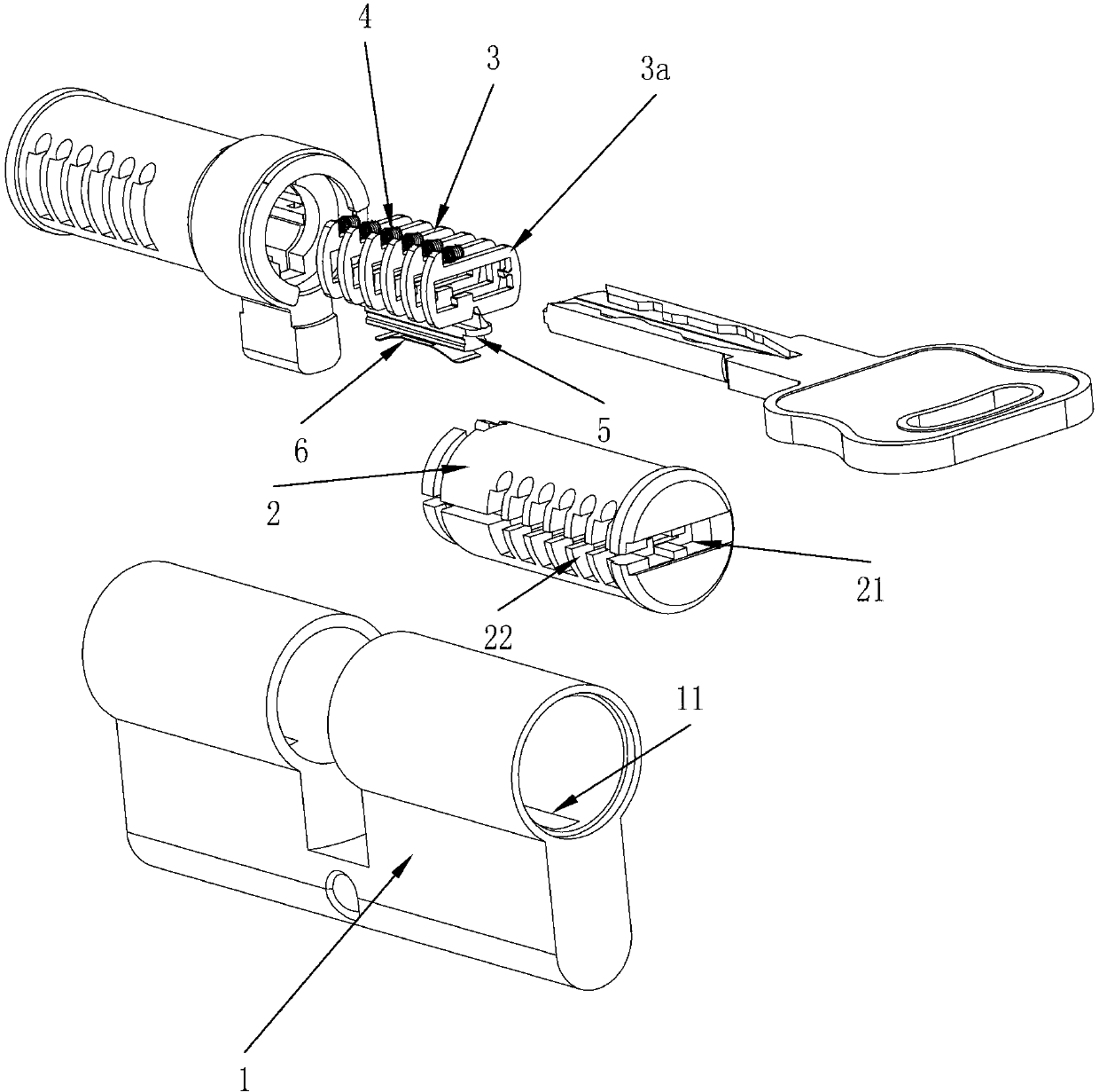
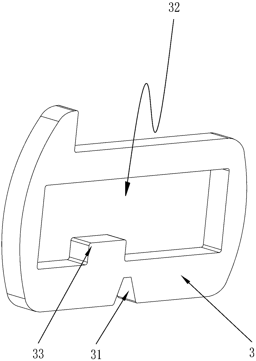
[0022] Such as figure 1 The engineering lock shown includes a lock case 1, in which a rotatable lock cylinder 2 is provided, a key hole 21 and a blade groove 22 are arranged in the lock cylinder 2, and a blade group 3 is placed in the blade groove 22 . Such as figure 2 A channel 32 for key insertion is provided on the blade group 3, a gap 31 is provided at the bottom of the blade group 3, and a number matching the tooth shape on the key for unlocking is provided on the inner wall of the channel 32. The sheet 33 is provided with a flange on the upper part of the blade set 3 . A groove 11 is provided in the lock housing 1, and a side pin 5 for clamping the blade 3 and an elastic member 6 that can lift the side pin 5 and make it fully enter the lock cylinder 2 to realize unlocking are also provided. Part 6 is a shrapnel, which includes engineering blades 3a in the blade group 3, such as image 3 A destruction structure 34 is provided on the engineering blade 3a. Before the d...


PUM


Abstract

The invention discloses an engineering lock comprising a lock shell (1). A rotatable lock cylinder (2) is arranged in the lock shell (1), a key hole (21) and blade slots (22) are arranged in the lock cylinder (2), and blade groups (3) are arranged in the blade slots (22). The engineering lock is characterized in that the blade groups (3) include engineering blades (3a), and a breakage structure (34) is arranged on the engineering blades (3a).The blade groups (3) can be unlocked by both an engineering key and a user key before the breakage structure is broken, and the blade groups (3) can be unlocked and the lock cylinder (2) can be rotated only by the user key after the breakage structure is broken. A rebounding device (4) is arranged in the lock cylinder (2) to push the blade groups (3) to be reset.

Description

【Technical field】 [0001] The invention relates to an engineering lock. 【Background technique】 [0002] When people buy a new house, they usually ask a decoration company to come to them for decoration. During the decoration period, they must give the key of the house to the decoration personnel. Everyone knows that the engineering lock is divided into two keys: the user key and the engineering key. The engineering key is given to the decoration personnel, and the user key remains. It is for the user to use. After the house decoration is completed, the owner uses the user key to open the door once, and the engineering key becomes invalid and can no longer open the door. [0003] Chinese patent CN200610082172.3 discloses an anti-technical and anti-damage engineering lock head, which is provided with engineering pins in the lock end of the lock cylinder, or in the lock end with pins, and the end face of the pins on the engineering pins that is in contact with the key is placed ...

Claims


Application Information

Patent Timeline
IPC IPC(8): E05B35/08E05B29/10E05B15/14
Inventor 沈强
Owner 沈强
Why Eureka
Try Eureka