Buckle-type nut component

A snap-on, nut technology, applied in the direction of nuts, threaded fasteners, connecting components, etc., can solve problems such as thermal deformation, achieve convenient operation, good sealing effect, and ensure the effect of sealing effect

Active Publication Date: 2013-06-05
ANHUI JIANGHUAI AUTOMOBILE GRP CORP LTD
View PDF7 Cites 8 Cited by
  • Summary
  • Abstract
  • Description
  • Claims
  • Application Information

AI Technical Summary

Problems solved by technology

[0003] The purpose of the present invention is to overcome the above problems and provide a snap-on nut assembly that can be conveniently connected by bolts and nuts without welding, avoiding thermal deformation caused by welding, and is especially suitable for use in narrow spaces or on one side of the connected parts Connection of panel parts in closed case

Method used


Image

  • Buckle-type nut component
  • Buckle-type nut component
  • Buckle-type nut component

Examples


Embodiment Construction

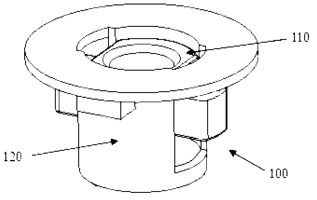
[0036] refer to figure 1 , the nut body 110 and the tubular member 120 are two separate components that are assembled together to form the nut assembly 100 .

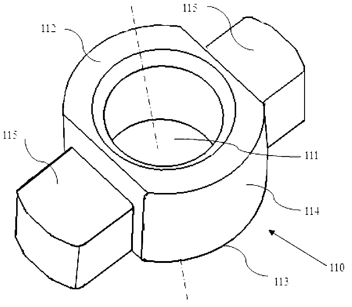
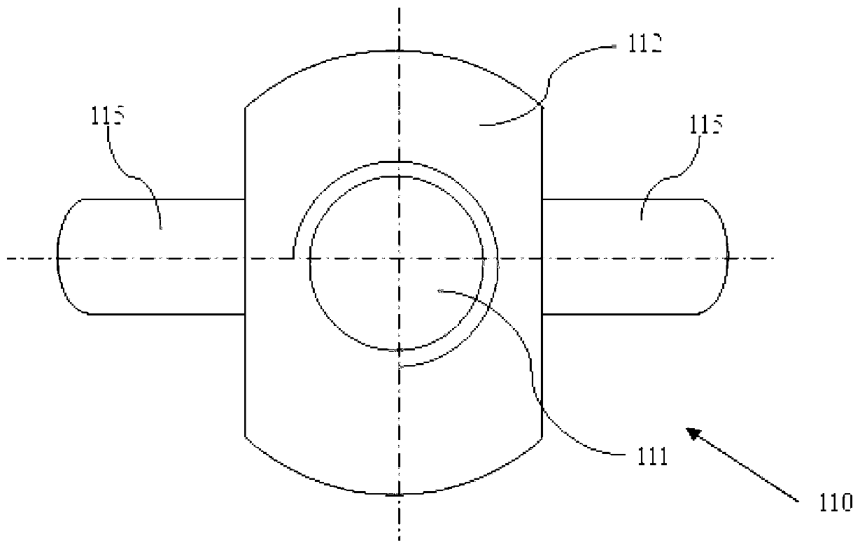
[0037] to combine figure 2 , image 3 and Figure 4 , which shows the specific structure of the nut body 110 in detail. Same as common nuts, the nut body 110 has a threaded hole 111 , an upper end surface 112 , a lower end surface 113 and a side wall 114 . Different from common nuts, there are two protruding wing-shaped portions 115 on the side wall 114 of the nut body 110 . The wing 115 also has an upper end face 1151 and a lower end face 1152 .

[0038] to combine Figure 5 , Image 6 and Figure 7 , which shows the specific structure of the tubular member 120 in detail. The tubular member 120 has two ends, one end is marked as 121 (ie, the upper end 121 in the figure), and the other end is marked as 122 (ie, the lower end 122 in the figure). The outer wall 123 of the tubular member 120 has flanges 126 arra...


PUM


Abstract

The invention provides a buckle-type nut component comprising a nut body and a tubular unit. A protruding wing-shaped unit is arranged on the side wall of the nut body, and the outer wall of the tubular unit is provided with a flange arranged in a circumference direction. A limit groove, extending axially from one end of the tubular unit and penetrating through a plain on the upper surface of the flange and the plain on the lower surface of the flange, is reserved in the tubular unit. One end of the limit groove is open, while the other end of the limit groove is sealed. The wing-shaped unit of the nut body enters the limit groove from an open end of the limit groove, and extends out of the limit groove, so that the nut body is limited in the tubular unit, and a gap is reserved between the upper end surface of the wing-shaped unit and the lower end surface of the flange. The buckle-type nut taken place by a projection welding nut has the advantages of convenience in buckle connection operation and high intensity of connection with the nut. The nut component can be reused, and thermal deformation of a connector caused by welding is simultaneously avoided.

Description

technical field [0001] The invention relates to the field of mechanical connectors, in particular to a buckle-type nut assembly in which a nut cooperates with a tubular member. Background technique [0002] Bolt and nut connections are often used in the mechanical field. Usually, holes are opened on the connected parts, and then the nuts are placed on one side of the connected parts. The bolts are inserted into the through holes from the other side and screwed into the nuts. Connection operation. In a narrow space, or when one side of the connected part is closed, when the bolt and nut connection is used, it can only be operated from one side. At this time, the nut is usually projected on the connected part first, and then screwed in. bolt. However, when the connected parts are thinner plates, such as automobile sheet metal parts, welding is likely to cause deformation of the sheet metal parts, and when the connected parts are non-metallic materials such as plastics, weldi...

Claims


Application Information

Patent Timeline
Patent Type & Authority Applications(China)
IPC IPC(8): F16B37/04F16B37/16
CPCF16B37/04F16B37/042
Inventor 吴根忠康春香李永王香廷卫刚
Owner ANHUI JIANGHUAI AUTOMOBILE GRP CORP LTD
Why Eureka
Try Eureka