
Test equipment for electromagnetic immunity to interference

A technology of electromagnetic immunity and testing equipment, which is applied to electromagnets, electromagnets without armatures, circuits, etc., and can solve problems such as inaccurate test results

Inactive Publication Date: 2013-06-05
HONG FU JIN PRECISION IND (SHENZHEN) CO LTD +1
View PDF0 Cites 6 Cited by
  • Summary
  • Abstract
  • Description
  • Claims
  • Application Information

AI Technical Summary

Problems solved by technology

The magnetic field space should be a relatively uniform magnetic field environment, otherwise it will easily lead to inaccurate test results

Method used


Image

  • Test equipment for electromagnetic immunity to interference
  • Test equipment for electromagnetic immunity to interference
  • Test equipment for electromagnetic immunity to interference

Examples


Embodiment Construction

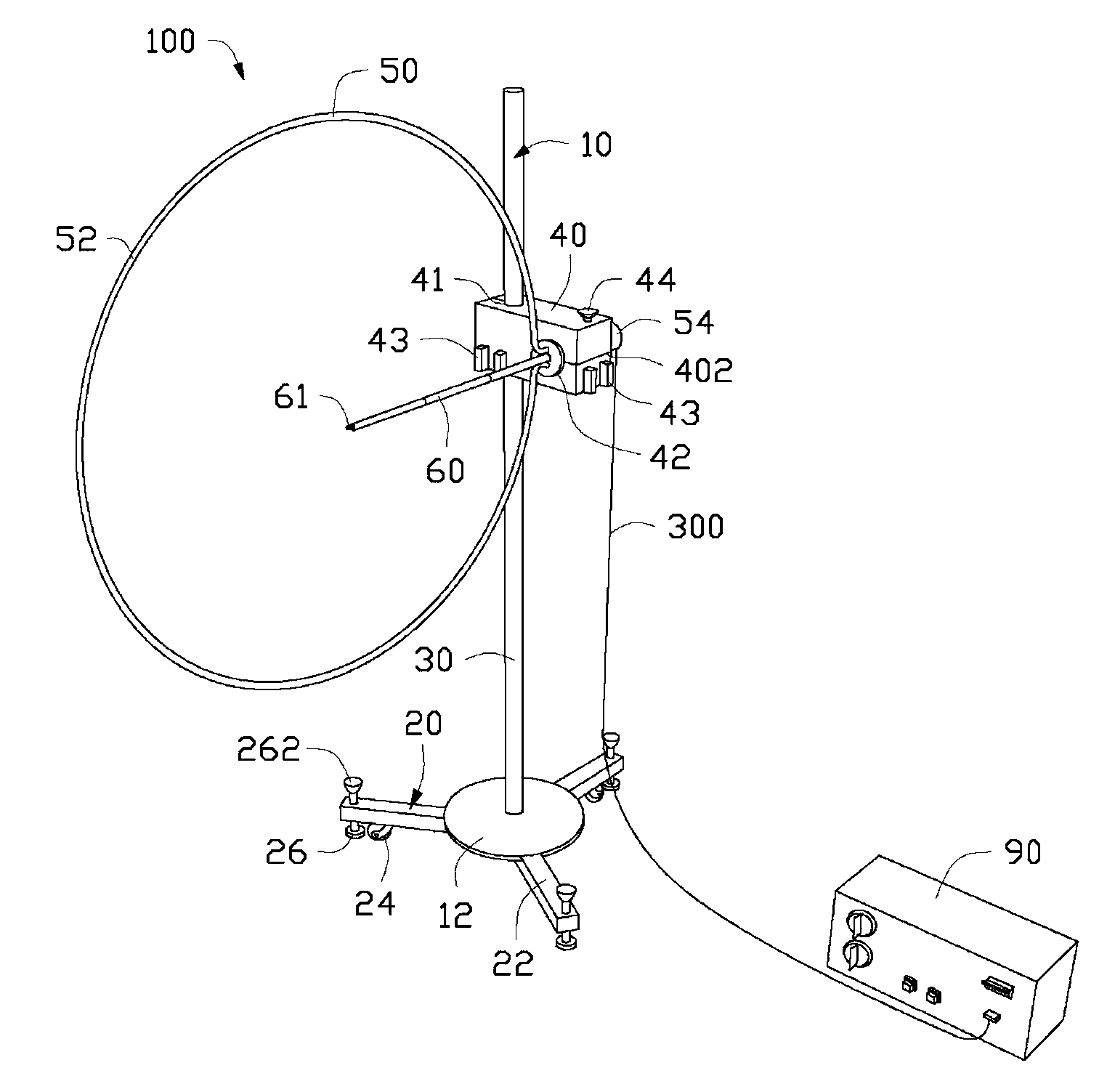
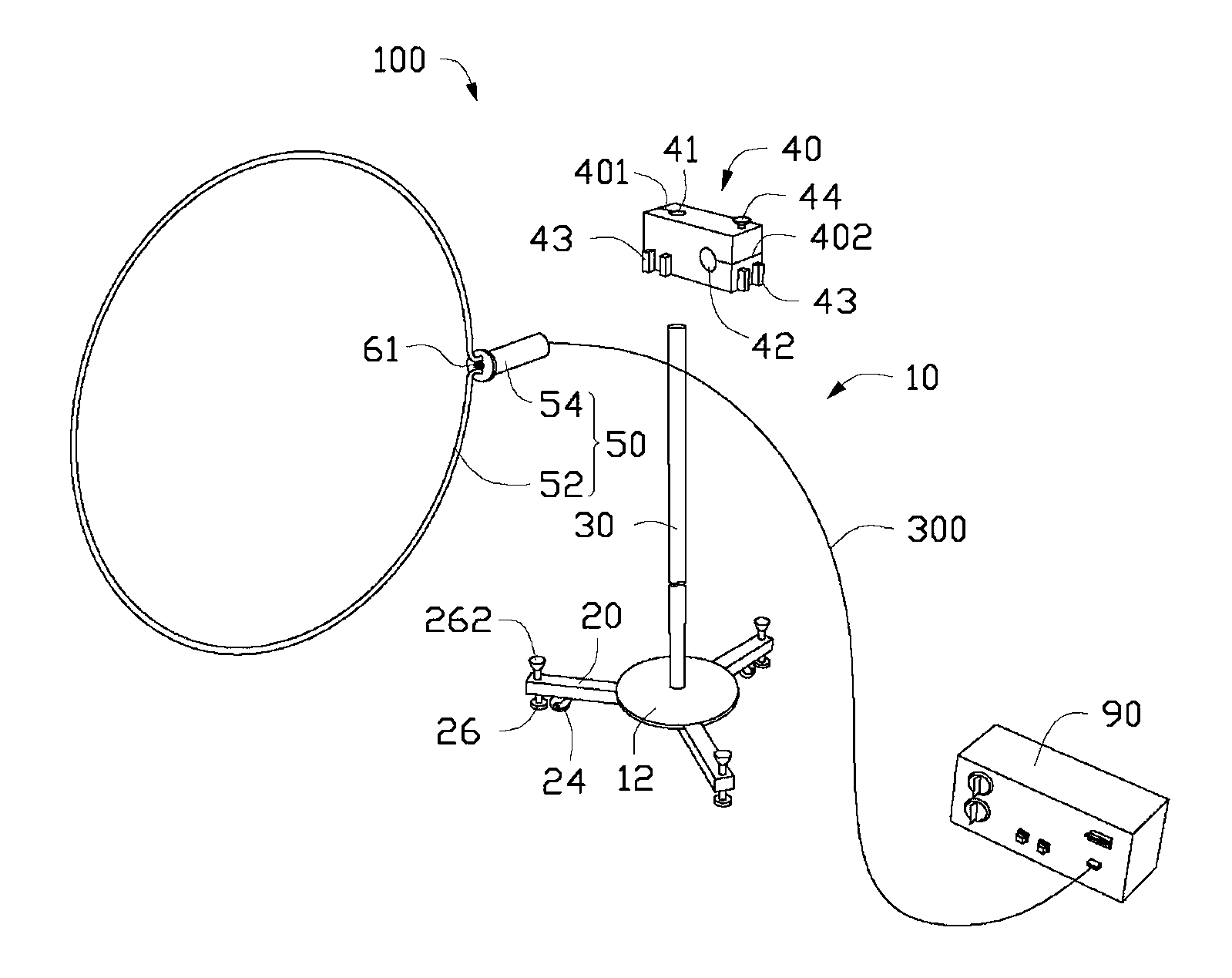
[0014] See figure 1 and figure 2 The electromagnetic immunity test equipment 100 of the preferred embodiment of the present invention includes a support portion 10, an induction coil 50, and an instrument box 90. The induction coil is carried on the bracket 10 and is electrically connected to the instrument box 90.

[0015] The bracket part 10 includes a base 12, a foot stand 20 connected to the base 12, a column 30 disposed on the base 12, a bearing block 40 slidably connected to the column 30, and a support frame 60 connected to the bearing block 40 .

[0016] The base 12 has a circular plate structure. The tripod 20 includes at least three rod-shaped support legs 22 and a sliding wheel 24 and a fixed foot 26 mounted on each support leg 22. The supporting legs 22 are fixed to the side of the base 12 at intervals to stably support the base 12. The sliding wheel 24 is arranged at an end of the supporting leg 22 away from the base 12, and the sliding wheel 24 is used to move the...


PUM


Abstract

Provided is test equipment for electromagnetic immunity to interference. The test equipment for the electromagnetic immunity to interference comprises a support part, an induction coil and an instrument container, wherein the instrument container is connected with the induction coil in an electrical mode, the support part comprises a carrier block and a support, a clamping groove used for carrying a body of a gauss meter is formed in at least one side face of the carrier block, the induction coil comprises an annual coil and a connector used for mounting the annual coil on the carrier block, the support is mounted on the connector and extends into the annual coil along the radial direction of the annual coil, and the tail end of the support carries a probe of the gauss meter and can be adjusted to any position between the center position of the annual coil and the connector.

Description

Technical field [0001] The invention relates to an electromagnetic immunity test equipment. Background technique [0002] In the electromagnetic compatibility (EMC) power frequency magnetic field (PFMF) immunity test, the induction coil is usually used as one of the main test instruments. During the test, the induction coil is connected with a current source, and the current source energizes the induction coil, and the induction coil generates a magnetic field of a certain intensity and a certain frequency in the space enclosed by it. Generally, the operator holds the Gauss meter in a hand and places it in the space surrounded by the induction coil to measure the intensity of the induced magnetic field generated by it, which causes certain damage to the operator's body. Place the object under test, generally household, commercial and industrial electrical and electronic equipment, in the magnetic field space to verify the magnetic field immunity of the object under test. The ma...

Claims


Application Information

Patent Timeline
Patent Type & Authority Applications(China)
IPC IPC(8): G01R31/00
CPCH01F13/00H01F7/20H01F7/202
Inventor 何小练
Owner HONG FU JIN PRECISION IND (SHENZHEN) CO LTD
Learn More