Card-poking mechanism with pressuring function and card sender using the same

A card issuing machine and functional technology, applied in the direction of instruments, ticketing equipment, etc., can solve the problems of increasing the power of the reel, easy plastic deformation of the tension spring, and increasing the wear of the reel, so as to reduce the wear of the reel, reduce the power of the reel, and extend the The effect of service life

Inactive Publication Date: 2013-06-05
GUANGDONG ELECTRONICS TECH RES INST
View PDF6 Cites 8 Cited by
  • Summary
  • Abstract
  • Description
  • Claims
  • Application Information

AI Technical Summary

Problems solved by technology

Since most of the currently used cards are thin cards with a thickness of only about 0.7-0.9mm, when a card is sent away, the step distance for feeding the card on the card pallet is only one card thick, which belongs to fretting, while the card output The opening is a narrow slit that is only slightly larger than the thickness of a card. Due to the spring characteristics (extension spring is easy to deform plastically, compression spring is easy to lose stability) and the frictional resistance of the card box, there are often problems of insufficient card feeding and card dialing. Phenomenon
If the feeding card is not in place, it is easy to cause the card dial to be hooked empty or stuck at the lower edge of the card outlet, and the card cannot be issued. When the entrance comes out of the bayonet, the next card will squeeze the first card under the spring force of the card feeding mechanism, which not only increases the wear of the roller of the card transport mechanism, but also increases the rolling force required by the roller

Method used


Image

  • Card-poking mechanism with pressuring function and card sender using the same
  • Card-poking mechanism with pressuring function and card sender using the same
  • Card-poking mechanism with pressuring function and card sender using the same

Examples


Embodiment 1

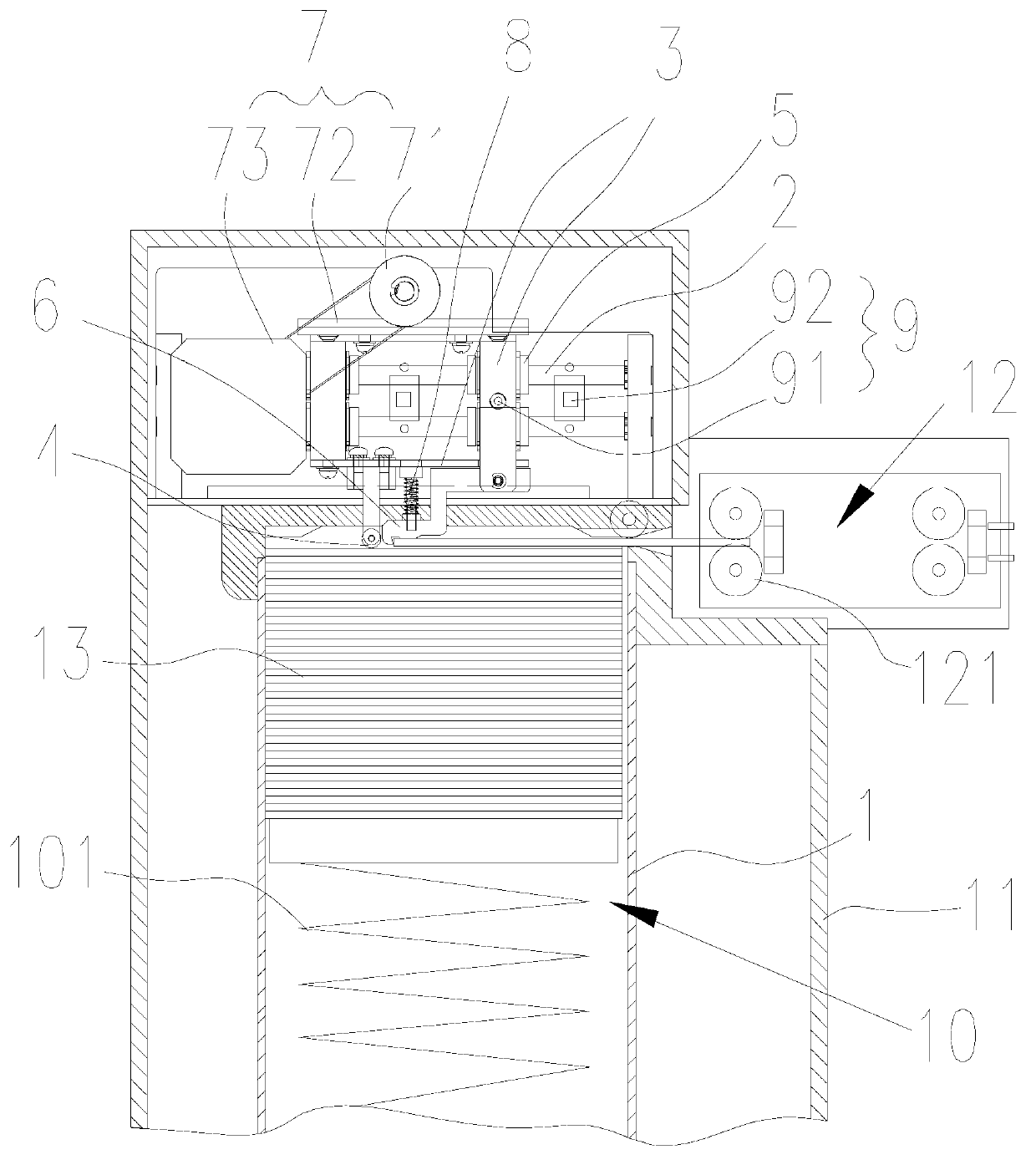
[0025] Such as figure 1 The shown card dialing mechanism with the function of applying pressure includes a guide rail 2, a slider 3, a linear reciprocating mechanism 7 and a detection device for detecting the moving position of the slider 3, all of which are installed on the card issuing machine chassis 9.

[0026] The linear reciprocating mechanism 7 of the present embodiment includes a gear 71, a rack 72 and a motor 73, the rack 72 is installed on the slider 3, the gear 71 is meshed with the rack 72, and the output shaft of the motor 73 is connected to the gear 71 through a pulley , the rotation of the motor 73 drives the gear 71 to rotate, and drives the slider 3 to perform horizontal linear reciprocating motion on the guide rail 2 .

[0027] The bottom of the slider 3 is provided with a pinch wheel 4 for pressing the next card in the card storage box 1 of the card issuer and a hook 6 for moving the first card in the card box 1 of the card issuer. The pinch wheel 4 can It...

Embodiment 2

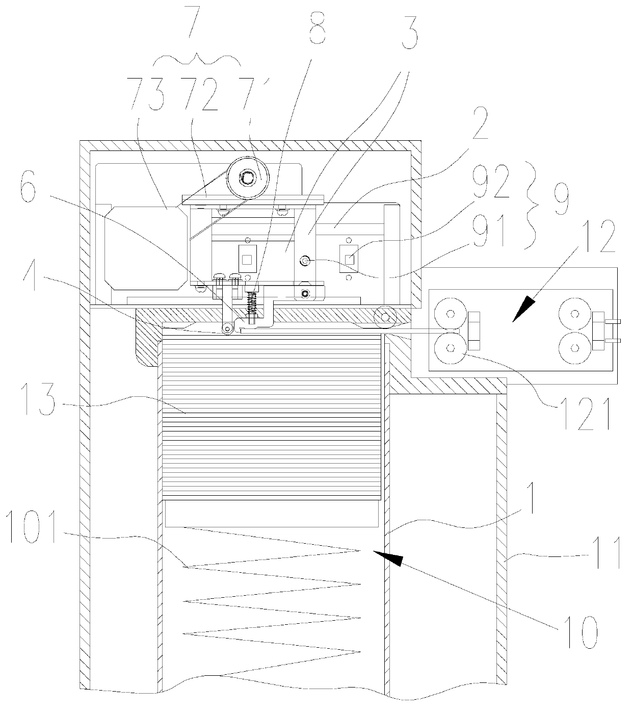
[0034] Such as figure 2 Shown is the second embodiment of the present invention, the difference between the second embodiment and the first embodiment is that the linear bearing 5 is omitted. The guide rail 2 is a linear guide rail, and a groove of the guide rail 2 is provided on the slider 3 to be slidably connected with the linear guide rail, which simplifies the structure and can also realize the linear reciprocating motion of the slider 3 .

Embodiment 3

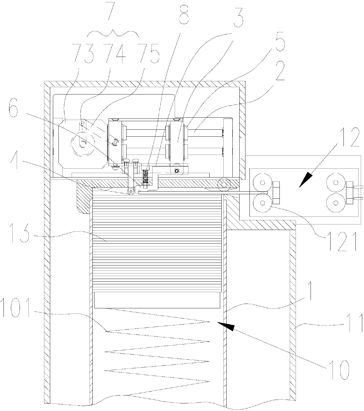
[0036] Such as image 3 Shown is the third embodiment of the present invention. The difference between the third embodiment and the first embodiment is that the detection device 9 is omitted, and the movement position of the slider 3 is limited by controlling the start and stop of the motor 73 .

[0037]Linear reciprocating mechanism 7 comprises crank 74, connecting rod 75 and motor 73, and connecting rod 75 is hinged with slide block 3, and crank 74 is installed on the output shaft of motor 73 and forms crank-rocker mechanism with connecting rod 75, and motor 73 drives crank 74 rotates to drive the connecting rod 75 to swing, and then drives the slider 3 to reciprocate linearly on the guide rail 2 through the linear bearing 5.


PUM


Abstract

The invention discloses a card-poking mechanism with a pressuring function. The card-poking mechanism with the pressuring function comprises a guide rail, a sliding block and a straight reciprocating motion mechanism, wherein the guide rail, the sliding block and the straight reciprocating motion mechanism are all installed on a case of the card sender. The straight reciprocating motion mechanism drives the sliding block to move straightly in a reciprocating mode in the guide rail. A pressure wheel used for pressuring a second card in a card storage case of the card sender and a card hook used for poking a first card in the card storage case of a card sender are arranged on the sliding block, wherein the pressure wheel is connected on the sliding block in a rotatable mode and is placed at the back of the poking direction of the card hook. The horizontal plane which the bottommost portion of the pressure wheel is located in is lower than the horizontal plane which the bottommost portion of the card hook is located in, so that a gap between the first card and the second card is formed. The invention further discloses the card sender using the card-poking mechanism with the pressuring function. By pressuring the second card to form the gap between the first card and the second card, the card-poking mechanism with the pressuring function and the card sender using the card-poking mechanism enable the poking of the card to be accurate and in place.

Description

technical field [0001] The present invention relates to a card-pushing mechanism of a card issuing machine, in particular to a card-pushing mechanism with a pressure-applying function, and also relates to a card-issuing machine using the above-mentioned card-pushing mechanism. Background technique [0002] Unattended card issuing machines are widely used in highway toll collection systems, especially in highway toll collection systems. Drivers use card issuing machines to self-check their cards, which improves the efficiency of highway traffic and reduces operating costs. However, since the entrance lane using the unattended automatic card issuing machine does not require personnel intervention and needs to operate uninterrupted for 24 hours, relatively high requirements are put forward for the reliability of the card issuing machine. [0003] Existing card issuing machines include a chassis, a card storage box for containing cards (the card box can also be integrated with a...

Claims


Application Information

Patent Timeline
Patent Type & Authority Applications(China)
IPC IPC(8): G07B15/00
Inventor 徐青平翁名涛
Owner GUANGDONG ELECTRONICS TECH RES INST
Why Eureka
Try Eureka