
A circuit for power compensation by bias current in a radio frequency power amplifier

A power amplifier and bias current technology, applied in power amplifiers, high-frequency amplifiers, improved amplifiers to reduce temperature/power supply voltage changes, etc., can solve problems such as output power reduction

Active Publication Date: 2016-06-08
GUANGZHOU HUIZHI MICROELECTRONICS
View PDF10 Cites 0 Cited by
  • Summary
  • Abstract
  • Description
  • Claims
  • Application Information

AI Technical Summary

Problems solved by technology

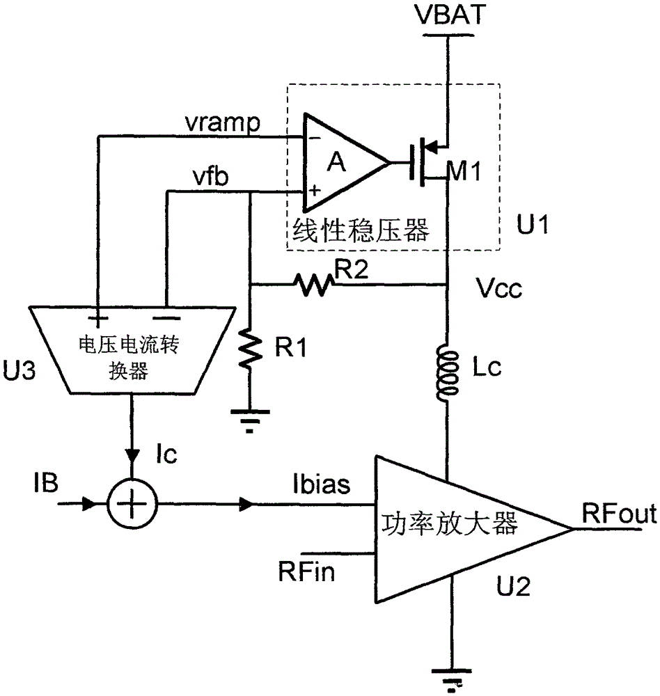
[0005] The invention adopts a circuit for power compensation through bias current in a radio frequency power amplifier to solve the problem of output power reduction when the bias voltage of the power supply is reduced, and the circuit detects the voltage difference between the control voltage of the linear regulator and the feedback terminal , the bias current used to compensate is controlled by this voltage difference

Method used


Image

  • A circuit for power compensation by bias current in a radio frequency power amplifier
  • A circuit for power compensation by bias current in a radio frequency power amplifier
  • A circuit for power compensation by bias current in a radio frequency power amplifier

Examples


Embodiment Construction

[0018] Embodiments of the present invention will be described below through specific examples. Those skilled in the art can easily understand other advantages and effects of the present invention from the content disclosed in this specification. The present invention can also be implemented or applied through other different specific embodiments. Various modifications or changes may be made to the details in this specification based on different viewpoints and applications without departing from the spirit of the present invention.

[0019] Figure 4 A specific embodiment of a circuit for power compensation through bias current in a radio frequency power amplifier is given, the circuit mainly includes a linear voltage regulator U1, an HBT power amplifier tube U2, and detects the input voltage difference of the linear voltage regulator U1 and converts it A voltage-to-current converter U3 that converts to compensation current. The power input of the linear voltage regulator U...


PUM


Abstract

The invention discloses a circuit capable of conducting compensation through a bias current in a radio frequency power amplifier. The circuit is used for solving the problem that when bias voltage of a power source is reduced, output power is reduced, control voltage of a circuit detection linear voltage stabilizer and a voltage difference of a feedback end are controlled by the voltage difference to be used for compensating size of the bias current, and when the bias voltage of the power source is higher than preset value, the control voltage of the linear voltage stabilizer and the voltage difference of the feedback end are quite small, and a compensation current is close to zero. When the bias voltage of the power source is close to or inferior to the preset value, a voltage difference between the control voltage and feedback voltage of the linear voltage stabilizer and is increased. A voltage current converter is utilized to convert the voltage difference into a current according to a certain relation and add to a bias current of the radio frequency power amplifier, and the bias current of the radio frequency power amplifier is further increased to compensate effect of reducing of the bias voltage of the power source on the output power.

Description

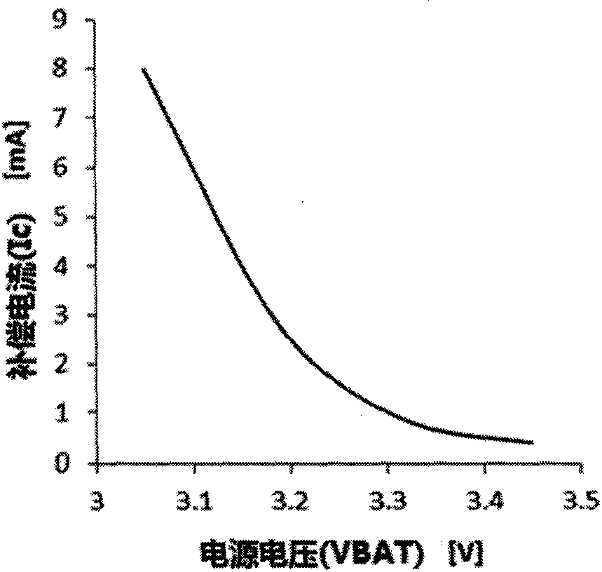
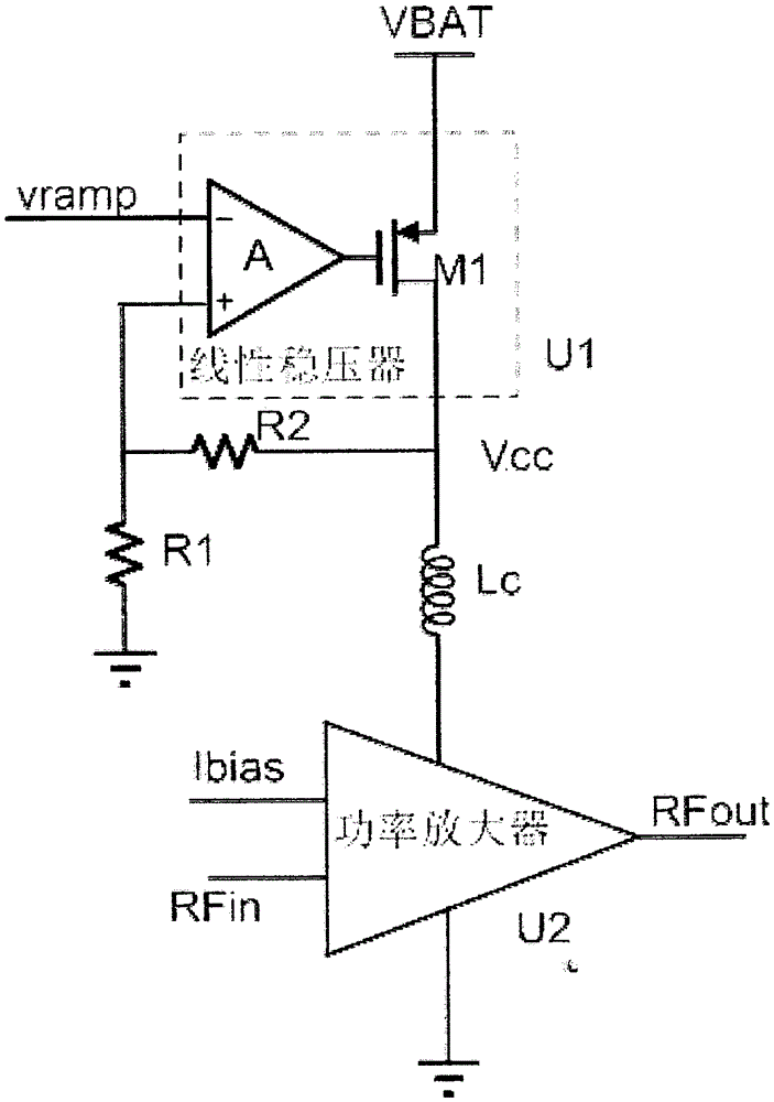
technical field [0001] The invention relates to a semiconductor integrated circuit, in particular to a circuit for power compensation through bias current in a radio frequency power amplifier. Background technique [0002] RF power amplifiers can be divided into linear power amplifiers and saturated power amplifiers. Linear power amplifiers have a certain power gain within the normal operating range, and their output power is determined by the input power. A saturated power amplifier generally works in a power saturation state, and its output power is mainly determined by the bias voltage of the power supply at the signal output point of the power output tube, and is also affected by the static bias current. [0003] In order to obtain a stable power supply bias voltage to ensure constant output power, the traditional design method uses a linear regulator to generate an output power supply bias voltage Vcc proportional to the input control voltage vramp, such as figure 1 sh...

Claims


Application Information

Patent Timeline
Patent Type & Authority Patents(China)
IPC IPC(8): H03F3/20H03F3/189H03F1/30
Inventor 李一男
Owner GUANGZHOU HUIZHI MICROELECTRONICS
Learn More