Radio frequency power amplifier with high linearity and high efficiency

A radio frequency power, high-efficiency technology, applied in high-frequency amplifiers, power amplifiers, etc., can solve problems such as limited effects, and achieve the effects of increasing amplitude, enhancing the ability to resist breakdown, high linearity and high efficiency

Active Publication Date: 2013-05-29
BEIJING MXTRONICS CORP +1
View PDF3 Cites 11 Cited by
  • Summary
  • Abstract
  • Description
  • Claims
  • Application Information

AI Technical Summary

Problems solved by technology

But only choose the type of work, the effect is limited, to take into account the high linearity and high efficiency, only to design a new circuit structure

Method used


Image

  • Radio frequency power amplifier with high linearity and high efficiency
  • Radio frequency power amplifier with high linearity and high efficiency
  • Radio frequency power amplifier with high linearity and high efficiency

Examples


Embodiment Construction

[0023] Below in conjunction with accompanying drawing and specific embodiment the present invention is described in further detail:

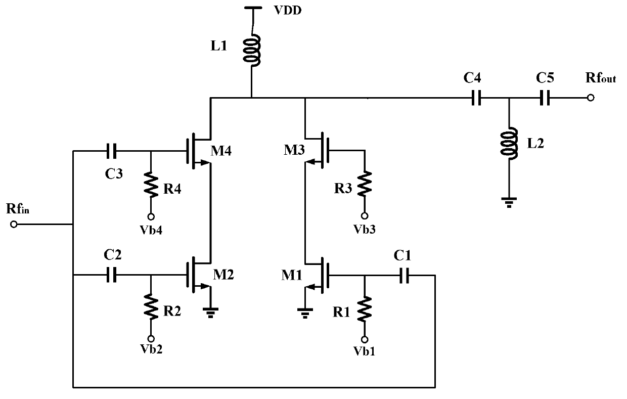
[0024] Such as figure 2 Shown is a schematic diagram of the topological structure of the high linearity and high efficiency radio frequency power amplifier of the present invention, the radio frequency power amplifier of the present invention includes five capacitors C1, C2, C3, C4, C5, four resistors R1, R2, R3, R4, four NMOS transistors M1, M2, M3, M4, two inductors L1, L2, the specific connection relationship is: the input RF signal Rfin is respectively connected to one end of the capacitor C1, one end of the capacitor C2 and one end of the capacitor C3; the other end of the capacitor C1 is connected to the NMOS tube M1 The other end of the capacitor C2 is connected to the gate of the NMOS transistor M2, and the other end of the capacitor C3 is connected to the gate of the NMOS transistor M4; the bias voltage Vb1 is connected to one end of t...


PUM


Abstract

The invention discloses a radio frequency power amplifier with high linearity and high efficiency. The radio frequency power amplifier with high linearity and high efficiency comprises five capacitors: C1, C2, C3, C4 and C5, four resistances: R1, R2, R3 and R4, four N-channel metal oxide semiconductor (NMOS) pipes: M1, M2, M3 and M4 and two inductances: L1 and L2. Input radio frequency signals (Rfin) are respectively input to grids of the M1, M2 and M4 NMOS pipes through the C1, C2 and C3 capacitors, Vb1, Vb2, Vb3 and Vb4 bias voltages respectively provide direct current to the M1, M2, M3 and M4 NMOS pipes through the R1, R2, R3 and R4 resistances, drain electrode of the M2 NMOS pipe is connected with source electrode of the M4 NMOS pipe, and drain electrode of the M1 NMOS pipe is connected with source electrode of the M3 NMOS pipe. The radio frequency power amplifier with high linearity and high efficiency enhances puncture-resisting performance of a transistor, improves output power, and achieves high linearity and high efficiency of the power amplifier.

Description

technical field [0001] The invention belongs to the technical field of wireless communication systems and relates to a radio frequency power amplifier with high linearity and high efficiency. Background technique [0002] With the increasing demand of the wireless communication market, the development and research of radio frequency integrated circuits have been developed rapidly. In the radio frequency transmitter integrated circuit system, the power amplifier is located at the front end of the transmission system and is also one of the modules with the largest power consumption. How to output power efficiently while ensuring linearity is still a hot spot in the research of radio frequency power amplifiers today. and difficult. In terms of process selection, although SiGe, InP, GaAs and other processes can manufacture higher-performance power amplifier circuits, their cost is much higher than that of CMOS processes, and it is difficult to achieve full integration of digita...

Claims


Application Information

Patent Timeline
Patent Type & Authority Applications(China)
IPC IPC(8): H03F3/189H03F3/20
Inventor 魏慧婷侯训平文武
Owner BEIJING MXTRONICS CORP
Why Eureka
Try Eureka