Fast clamping device in new energy automobile motor testing system

A new energy vehicle, motor testing technology, applied in workpiece clamping devices, manufacturing tools, etc.

Inactive Publication Date: 2013-06-12
QINGDAO UNIV OF SCI & TECH
View PDF4 Cites 9 Cited by
  • Summary
  • Abstract
  • Description
  • Claims
  • Application Information

AI Technical Summary

Problems solved by technology

[0002] The dynamometer is also called a dynamometer, which is mainly used to test the power of the engine, and can also be used as a loading device for the reducer and gearbox to test their transmission Power, mainly divided into hydraulic dynamometers, eddy current dynamometers, and electric dynamometers. Among them, the control performance and response speed of eddy current dynamometers are significantly better than those of hydraulic dynamometers, but hydraulic and eddy current dynamometers are Pure energy consumption test equipment, which does not meet the needs of modern energy conservation and environmental protection, will definitely withdraw from the market. With the widespread attention of new energy and new power, electric dynamometers are favored because energy can be fed back to the grid, energy saving and environmental protection, especially in today's In the era of very high product performance requirements, fast and convenient testing has become the primary requirement for improving production efficiency and reducing labor intensity
[0003]The existing new energy vehicle motor test system mainly uses the electric dynamometer test system, which uses AC frequency conversion feedback loading, and the loaded energy is fed back to the grid through the AC load motor , is widely used in the testing of various rotary equipment such as motors, generators, pumps, etc. The system is composed of the motor under test, the loading motor and various detection and control devices, and is used to test the speed, torque performance, and speed of the equipment under test. Response and torque ripple overshoot and other performance indicators provide factory inspection data for the use of the motor, but in the existing test system, the clamping device is installed by bolt connection, which cannot be automatically centered, and the installation and clamping takes a long time and the efficiency is low , high labor intensity, and high requirements for mechanical processing, hindering the popularization and use of motor test systems

Method used


Image

  • Fast clamping device in new energy automobile motor testing system
  • Fast clamping device in new energy automobile motor testing system
  • Fast clamping device in new energy automobile motor testing system

Examples


Embodiment Construction

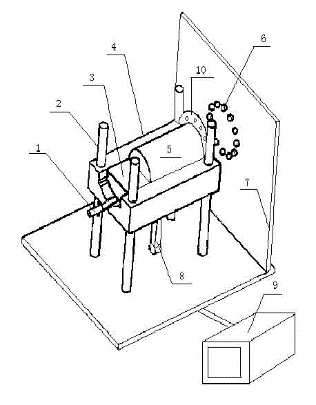
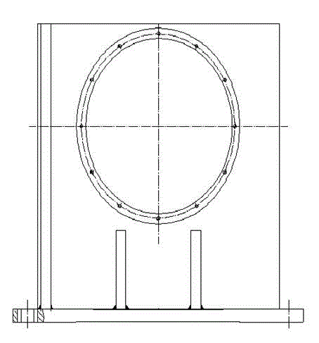
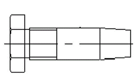
[0018] Further, the guide bolts 6 adopt a tapered structure and are provided in multiples, and are evenly distributed on the fixing bracket 7 around the circumference.

[0019] Further, a flange 10 is arranged on the fixing bracket 7 and fixed by guide bolts 6 .

[0020] Further, the lead screw pressing mechanism includes a lead screw 1 , a pressing block 3 connected to the threaded end of the lead screw 1 , and a servo motor connected to the optical axis of the lead screw 1 .

[0021] First, place the motor 5 under test in the self-centering V-shaped groove 4, and the height adjustment hydraulic cylinder 8 is driven by the hydraulic drive system 9 to adjust the height so that the center height of the motor 5 under test is equal to the center of the inner hole on the fixed bracket 7. Alignment, the left and right centers of the tested motor 5 are self-aligned by the self-centering V-shaped groove 4, and the self-centering V-shaped groove 4 is guided by four guide support colum...


PUM


Abstract

The invention discloses a fast clamping device in a new energy automobile motor testing system, which comprises a lead screw pressing mechanism, a V-shaped self-centering slot, a guide supporting column, a height-adjusting hydraulic cylinder, a guide bolt, a hydraulic driving system and a fixing bracket. The lead screw pressing mechanism is installed in the V-shaped self-centering slot; the guide supporting column is installed on the fixing bracket, and the upper part of the guide supporting column is connected with the V-shaped self-centering slot; the height-adjusting hydraulic cylinder is installed at the bottom of the V-shaped self-centering slot and connected with the hydraulic driving system, and a photoelectric sensor is arranged at the top end of the height-adjusting hydraulic cylinder; and the guide bolt is installed on the fixing bracket. The fast clamping device can rapidly and accurately achieve clamping, is wholly and automatically controlled, and does not require for manual intervention; the disassembly is extremely convenient; and the reliability and the practicability are high, the testing efficiency is greatly improved, the working environment of operators is improved, and a good testing platform is provided for testing of similar products.

Description

technical field [0001] The invention relates to a new energy vehicle motor testing device, in particular to a fast clamping device for new energy vehicle motor testing. Background technique [0002] The dynamometer is also called a dynamometer, which is mainly used to test the power of the engine, and can also be used as a loading device for a reducer and a gearbox to test their transmission power. It is mainly divided into a hydraulic dynamometer and an eddy current dynamometer. , Electric dynamometer, among them, the control performance and response speed of the eddy current dynamometer are obviously better than the hydraulic dynamometer, but the hydraulic and eddy current dynamometer are pure energy consumption test equipment, which do not meet the needs of modern energy conservation and environmental protection. It is bound to withdraw from the market. With the widespread attention of new energy and new power, electric dynamometer is favored because energy can be fed bac...

Claims


Application Information

Patent Timeline
Patent Type & Authority Applications(China)
IPC IPC(8): B25B11/00
Inventor 段俊勇王守城任海霞高伟
Owner QINGDAO UNIV OF SCI & TECH
Why Eureka
Try Eureka