Multi-terminal heat supply first type absorption heat pump

An absorption heat pump and multi-terminal heating technology, which is applied in the direction of adsorption machines, energy-saving heating/cooling, lighting and heating equipment, etc., can solve the problem of large temperature difference between the driving heat medium and the heated medium, the limitation of waste heat utilization rate, and the thermodynamic perfection Low-level problems, to achieve the effect of high thermodynamic perfection, full use of temperature difference, and high-performance index

Active Publication Date: 2015-08-12
李华玉
View PDF7 Cites 0 Cited by
  • Summary
  • Abstract
  • Description
  • Claims
  • Application Information

AI Technical Summary

Problems solved by technology

[0003] When the temperature range of the heated medium is wide, the first type of absorption heat pump with the absorber and condenser as the heat supply end will encounter the following problems: ①Limited by the nature of the solution, it is impossible to use the two heat supply ends to realize the heating of the heated medium. The demand for heating medium; ②The temperature difference between the driving heat medium and the heated medium is large, the thermodynamic perfection of the cycle is low, and the utilization rate of waste heat is limited; ③When the heat load of the absorber changes, the heat load of the condenser will follow Make corresponding changes, the two restrict each other in the provision of heat load, and cannot obtain a reasonable degree of thermodynamic perfection when the working conditions change; ④ When the driving heat medium is used to provide sensible heat, the high-temperature exothermic part of the driving heat medium It is different from the temperature difference between the low-temperature exothermic part and the heated medium, and the temperature difference between the high-temperature section of the driving heat medium and the low-temperature section of the heated medium is larger

Method used


Image

  • Multi-terminal heat supply first type absorption heat pump
  • Multi-terminal heat supply first type absorption heat pump
  • Multi-terminal heat supply first type absorption heat pump

Examples


Embodiment Construction

[0026] The first thing to explain is that in the expression of the structure and process, it will not be repeated if it is not necessary; the obvious process will not be expressed. The present invention will be described in detail below in conjunction with the accompanying drawings and examples.

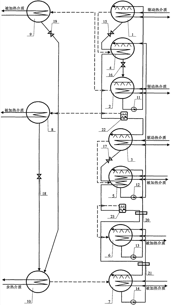
[0027] figure 1 The first type of absorption heat pump shown in the multi-terminal heating is realized as follows:

[0028] ① Structurally, it mainly consists of generator, second generator, third generator, absorber, second absorber, third absorber, fourth absorber, condenser, second condenser, evaporator, solution pump, second solution pump, third solution pump, fourth solution pump, solution throttle valve, second solution throttle valve, third solution throttle valve, throttle valve, second solution throttle valve, solution heat exchanger , the second solution heat exchanger, the steam distribution chamber and the second steam distribution chamber; the fourth absorber 7 has a d...


PUM


Abstract

The invention provides a multi-end heating first class absorption heat pump, belonging to the field of refrigeration and heat pump technology. The multi-end heating first class absorption heat pump mainly comprises a generator, a second generator, a third generator, an absorber, a second absorber, a third absorber, a fourth absorber, a condenser, a second condenser, an evaporator, a solution pump, a second solution pump, a third solution pump, a fourth solution pump, a solution throttle valve, a second solution throttle valve, a third solution throttle valve, a throttle valve, a second throttle valve, a solution heat exchanger, a second solution heat exchanger, a stream distribution chamber and a second stream distribution chamber, wherein a heating end is formed by the condenser, the second condenser, the second absorber, the third absorber and the fourth absorber; the solution generation process is formed by the generator, the second generator, the third generator, the absorber and the second absorber; and therefore, the multi-end heating first class absorption heat pump can be formed.

Description

Technical field: [0001] The invention belongs to the technical field of low-temperature waste heat utilization and heat pump / refrigeration. Background technique: [0002] The first type of absorption heat pump uses the temperature difference between the driving heat medium and the heated medium as the driving force. When the driving temperature difference is large, a double-effect or multi-effect process should be used to fully utilize the driving heat; any heat transfer link The waste of temperature difference will reduce the utilization rate of heat energy. Only by making full use of the temperature difference can a reasonable thermodynamic perfection be guaranteed. [0003] When the temperature range of the heated medium is wide, the first type of absorption heat pump with the absorber and condenser as the heat supply end will encounter the following problems: ①Limited by the nature of the solution, it is impossible to use the two heat supply ends to realize the heating o...

Claims


Application Information

Patent Timeline
Patent Type & Authority Patents(China)
IPC IPC(8): F25B15/02F25B27/02
CPCY02B30/625Y02A30/274
Inventor 李华玉
Owner 李华玉
Why Eureka
Try Eureka