Heat exchanger for vehicle

一种换热器、车辆的技术,应用在间接换热器、换热器类型、车辆部件等方向,能够解决无法有效地控制工作流体温度等问题

Active Publication Date: 2013-06-12
HYUNDAI MOTOR CO LTD
View PDF6 Cites 7 Cited by
  • Summary
  • Abstract
  • Description
  • Claims
  • Application Information

AI Technical Summary

Problems solved by technology

Therefore, the temperature of the working fluid cannot be effectively controlled

Method used


Image

  • Heat exchanger for vehicle
  • Heat exchanger for vehicle
  • Heat exchanger for vehicle

Examples


Embodiment Construction

[0049] Reference will now be made in detail to various embodiments of the invention, examples of which are illustrated in the accompanying drawings and described below. While the invention will be described in conjunction with exemplary embodiments, it will be understood that present description is not intended to limit the invention to those exemplary embodiments. On the contrary, the invention is intended to cover not only the exemplary embodiments, but also various alternatives, modifications, equivalents and other embodiments, which may be included within the spirit and scope of the invention as defined by the appended claims .

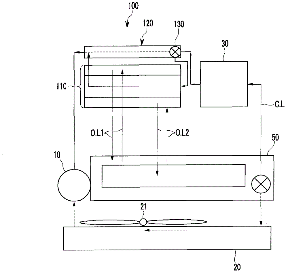
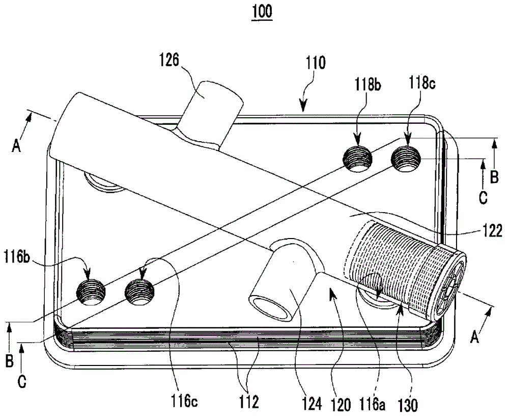
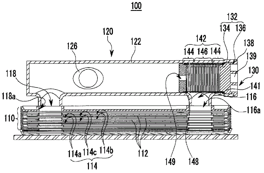
[0050] figure 1 is a schematic diagram of a cooling system of an exemplary automatic transmission to which a heat exchanger for a vehicle according to various embodiments of the present invention is applied; figure 2 is a perspective view of an exemplary heat exchanger for a vehicle according to various embodiments of the present invention; i...


PUM


Abstract

A heat exchanger may include a heat radiating portion provided with first, second, and third connecting lines formed in a predetermined sequence by stacking a plurality of plates, and receiving first, second, and third operating fluids respectively into the first, second, and third connecting lines, the first, second, and third operating fluids exchanging heat with each other while passing through the first, second, and third connecting lines and the first, second, and not being mixed with each other while being circulated, and a bifurcating portion connecting an inflow hole for flowing one operating fluid of the first, second, and third operating fluids with an exhaust hole for exhausting the one operating fluid, adapted for the one operating fluid to bypass the heat radiating portion according to a temperature of the one operating fluid, and mounted at an exterior of the heat radiating portion.

Description

[0001] Cross References to Related Applications [0002] This application claims priority from Korean Patent Application No. 10-2011-0129814 filed on Dec. 6, 2011, the entire contents of which are hereby incorporated by reference for all purposes. technical field [0003] The invention relates to a heat exchanger for a vehicle. More particularly, the present invention relates to a heat exchanger for a vehicle that can control the temperature of a working fluid flowing in the heat exchanger. Background technique [0004] Typically, heat exchangers transfer heat from a high temperature fluid to a low temperature fluid through heat transfer surfaces and are used in heaters, coolers, evaporators and condensers. [0005] Such heat exchangers reuse thermal energy, or control the temperature of a working fluid flowing therein for desired performance. The heat exchanger is used in an air conditioning system of a vehicle or a transmission oil cooler, and is installed in an engine r...

Claims


Application Information

Patent Timeline
Patent Type & Authority Applications(China)
IPC IPC(8): F28D1/00
CPCF01M5/002F01P2060/04F01P2060/045F16K31/002F28D9/005F28D9/0093F28D2021/0089F28F27/02B60H1/00B60H1/02F28D1/02F28D9/00F28F3/02F28F3/08F28F27/00
Inventor 金载然
Owner HYUNDAI MOTOR CO LTD
Why Eureka
Try Eureka