
Stereoscopic display device and its electronic device

A technology of a stereoscopic display device and a display panel, which is applied to stereoscopic systems, electrical components, static indicators, etc., can solve the problems of inability to meet stereoscopic images, a single optimal viewing distance for stereoscopic displays, etc., and achieve a good viewing effect.

Inactive Publication Date: 2015-10-28
华映视讯(吴江)有限公司 +1
View PDF4 Cites 0 Cited by
  • Summary
  • Abstract
  • Description
  • Claims
  • Application Information

AI Technical Summary

Problems solved by technology

[0004] When the same voltage is applied, the effective focal length (EFL) of the liquid crystal lens array is a certain value, resulting in only a single optimal viewing distance for the stereoscopic display
However, since different users have different sensitivities to 3D images, the optimal viewing distance may not be suitable for different users, thus failing to meet the needs of different users to enjoy the best stereoscopic images.

Method used


Image

  • Stereoscopic display device and its electronic device
  • Stereoscopic display device and its electronic device
  • Stereoscopic display device and its electronic device

Examples


Embodiment Construction

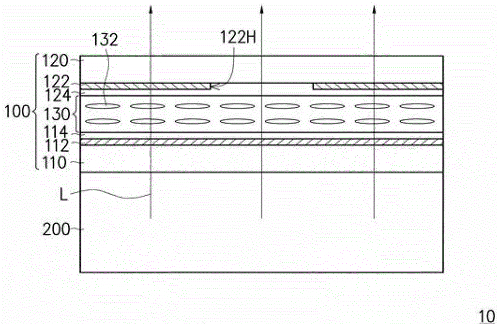
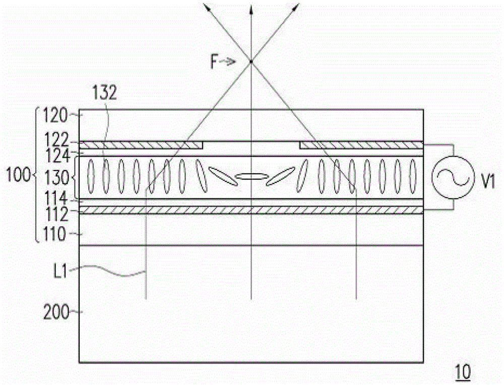
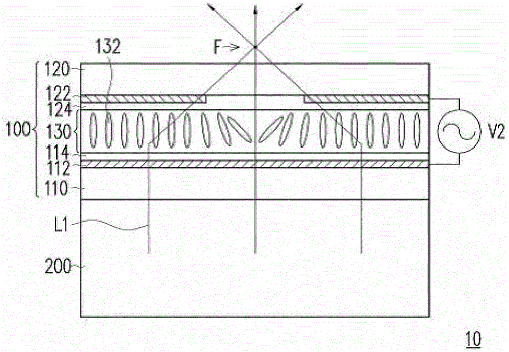
[0058] figure 1 It is a schematic cross-sectional view of a stereoscopic display device according to an embodiment of the present invention. figure 1 The three-dimensional display device 10 shown in FIG. 2 only shows the liquid crystal lens 100 and the display panel 200 and some components are omitted. Please refer to figure 1 The liquid crystal lens 100 includes a first substrate 110 , a first electrode layer 112 , a first alignment layer 114 , a second substrate 120 , a second electrode layer 122 , a second alignment layer 124 and a liquid crystal layer 130 . The first electrode layer 112 is disposed on the first substrate 110 . The first alignment layer 114 is disposed on the first electrode layer 112 . The second substrate 120 is opposite to the first substrate 110 . The second electrode layer 122 is disposed on the second substrate 120 and faces the first alignment layer 114 . The second alignment layer 124 is disposed on the second electrode layer 122 . The liquid ...


PUM


Abstract

The invention relates to a three-dimensional display device which comprises a display panel, a liquid crystal lens, an identification module and a driving circuit, wherein the display panel is used for outputting pictures; the liquid crystal lens is arranged on the display panel and is used for focusing the display light of the pictures on the focusing position; the identification module is used for capturing and identifying images, and outputting an identification signal according to the identification result; the driving circuit is electrically connected with the liquid crystal lens and the identification module; and the driving circuit is used for driving the liquid crystal lens to adjust the focusing position according to the identification signal.

Description

technical field [0001] The present invention relates to a display device and an electronic device, and in particular to a stereoscopic display device and an electronic device with the stereoscopic display device. Background technique [0002] When no voltage is applied to the liquid crystal lens, the long axis direction of the liquid crystal molecules is arranged according to the alignment direction of the alignment layer. At this time, when the light passes through the liquid crystal layer, the phase of the light will not be affected; when a voltage is applied to the liquid crystal lens, the liquid crystal molecules are driven and deflected by the electric field between the upper and lower electrode layers in the liquid crystal lens, where the electrode layer is located at the edge The electric field has a gradient change due to edge effects. Since the long axis direction of the liquid crystal molecules is aligned according to the direction of the electric field, when the ...

Claims


Application Information

Patent Timeline
Patent Type & Authority Patents(China)
IPC IPC(8): G02B27/22G02F1/29G02F1/133G06K9/00G09G3/36H04N13/00
Inventor 姜智尹张哲维
Owner 华映视讯(吴江)有限公司
Learn More