Check patentability & draft patents in minutes with Patsnap Eureka AI!

A fuel cell flow field plate and fuel cell

A fuel cell and flow field plate technology, applied in fuel cells, fuel cell parts, circuits, etc., can solve problems such as not considering the timely discharge of water, achieve good power generation performance, and reduce resistance

Active Publication Date: 2016-05-18
海宁经开产业园区开发建设有限公司
View PDF6 Cites 0 Cited by
  • Summary
  • Abstract
  • Description
  • Claims
  • Application Information

AI Technical Summary

Problems solved by technology

This kind of flow field plate does not take into account how to discharge the water generated in the reaction in time and avoid the problem of water accumulation on the catalytic reaction interface.

Method used


Image

  • A fuel cell flow field plate and fuel cell
  • A fuel cell flow field plate and fuel cell
  • A fuel cell flow field plate and fuel cell

Examples


Embodiment 1

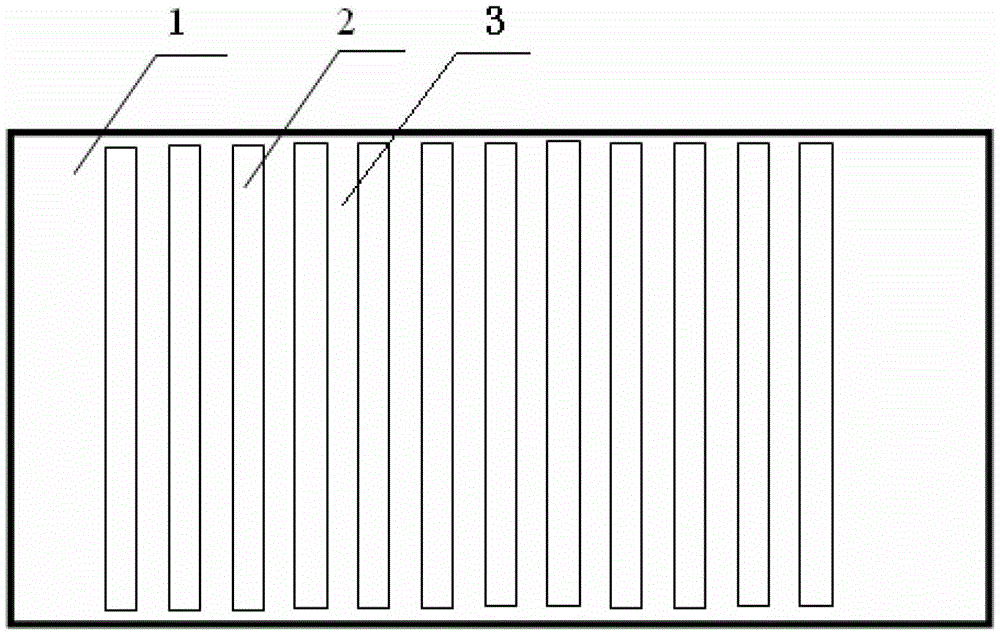
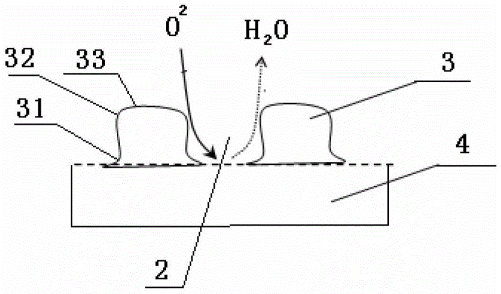
[0018] Such as figure 1 , 2 As shown, a fuel cell flow field plate includes a substrate 1 with a plurality of flow field channels 2, one end of the substrate 1 is bonded to the battery plate 4, the flow field channels 2 are arranged in parallel, and the flow field channels 2 are opened on the substrate 1 The part between the adjacent flow field channels 2 is the flow field skeleton 3; the end of the flow field skeleton 3 and the battery plate 4 is provided with a circular arc transition part 31, and the arc transition part 31 is connected to the flow field channel. 2 protrudes inside, and the end of the flow field frame 3 away from the battery plate is provided with a chamfer 32; the flow field frame 3 has a contact surface with the battery plate and an exposed surface in contact with the fluid, and the exposed surface is covered with a hydrophobic layer 33 .

[0019] The contact angle between the hydrophobic layer 33 and water is greater than 60 degrees. This contact angle...

Embodiment 2

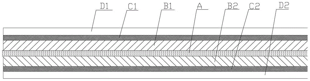
[0027] Such as Figure 1-3 As shown, a fuel cell includes a proton exchange membrane A, a battery anode plate B1 and a battery cathode plate B2 respectively arranged on both sides of the proton exchange membrane, flow field plates C1, C2 and battery splints D1, D2, each pole plate Connect a flow field plate, and each flow field plate is connected to a battery splint; the flow field plates C1 and C2 include a substrate 1 with multiple flow field channels 2, one end of the substrate 1 is attached to the battery plate, and the flow field channels 2 are arranged in parallel , the flow field channel 2 is a through groove opened on the substrate 1, and the part between the adjacent flow field channels 2 is the flow field skeleton 3; the end of the flow field skeleton 3 and the battery plate is provided with a circular arc transition part 31, The arc transition part 31 protrudes into the flow field channel 2, and the end of the flow field frame 3 away from the battery plate is provid...


PUM

PropertyMeasurementUnit
thicknessaaaaaaaaaa
radiusaaaaaaaaaa
lengthaaaaaaaaaa

Abstract

The invention discloses a flow field plate of a fuel cell. The flow field plate comprises a base plate which is equipped with a plurality of flow field channels; one end of the base plate is stuck to a cell polar plate; the flow field channels are arranged in parallel and are through grooves which are formed on the base plate; the parts between adjacent flow field channels are flow field frameworks; arc transition parts are arranged at the ends of the flow field frameworks which are stuck to the cell polar plate and extrude towards the interior of the flow field channels; chamfers are arranged at the ends of the flow field frameworks which are far away from the cell polar plate; the flow field frameworks are provided with a contact face which is stuck to the cell polar plate and an exposed face which is contacted with fluid; and the exposed face is covered with a hydrophobic layer. The invention discloses a fuel cell which comprises a proton exchange membrane, a cell positive plate and a cell negative plate which are arranged at two sides of the proton exchange membrane respectively, flow field plates and cell clamping plates. Each polar plate is connected a flow field plate and each flow field plate is connected with a cell clamping plate. The flow field plate and the fuel cell disclosed by the invention have the advantage of being capable of draining water in time in reaction.

Description

technical field [0001] The invention belongs to the field of fuel cells, in particular to a fuel cell flow field plate and a fuel cell using the flow field plate. Background technique [0002] A fuel cell is a device that directly converts chemical energy in fuel into electrical energy. The battery flow field plate is an important part of the fuel cell, which mainly plays the role of distributing fluid, conducting electricity and supporting the battery structure. Chinese Patent No. ZL200810163683.7 (CN101459246A) discloses a vein-shaped fuel cell flow field plate, which includes two combined flow field plates. There is a roughly square flow field area on the process plate, and the periphery of the flow field area is sealed. Gasket, the main vein for liquid inflow extends along the diagonal of the square, the confluence vein for liquid outflow is parallel to the side of the square, and perpendicular to the outlet of the liquid, one end of each branch is connected to the main...

Claims


Application Information

Patent Timeline
Patent Type & Authority Patents(China)
IPC IPC(8): H01M8/0258H01M8/026H01M8/0273H01M8/0276
CPCY02E60/50
Inventor 秦海英陈轩然刘嘉斌詹祥林杜诗欣郑佩云翁潇
Owner 海宁经开产业园区开发建设有限公司
Features
  • R&D
  • Intellectual Property
  • Life Sciences
  • Materials
  • Tech Scout
  • Unparalleled Data Quality
  • Higher Quality Content
  • 60% Fewer Hallucinations
Learn More