Polarization interference-based in-band optical signal-to-noise ratio detection method and device

A technology of optical signal-to-noise ratio and detection method, which is applied in the field of optical communication, can solve the problems of no longer flat noise spectrum, high difficulty, and high coherence of signal light, and achieve the effect of transparent signal modulation format and transmission rate

Inactive Publication Date: 2013-06-12
BEIJING UNIV OF POSTS & TELECOMM
View PDF6 Cites 24 Cited by
  • Summary
  • Abstract
  • Description
  • Claims
  • Application Information

AI Technical Summary

Problems solved by technology

With the increasing spectrum utilization, the introduction of resettable optical add-drop multiplexers and other devices in dense wavelength division multiplexing devices, and the different routes and filters for signals of different channels, the noise spectrum is no longer flat , the inter-channel noise power can no longer represent the true noise power, therefore, the traditional out-of-band OSNR measurement method is no longer applicable to current advanced optical network devices
[0003] In recent years, several in-band OSNR detection methods have been proposed, including: (1) Polarization nulling method, which obtains the maximum by rotating the polarizer under the premise that the signal is completely linearly polarized and the noise is completely unpolarized. and the minimum output optical power to calculate the OSNR. This method has nothing to do with the transmission rate and modulation format of the device, but it will be affected by Polarization Mode Dispersion (PMD) and birefringence effects. For devices with polarization mode dispersion , there will be a large measurement error; (2) Mach-Zehnder interferometer method, which is based on the high coherence of signal light and the incoherent characteristics of noise, by measuring the interference maximum value and interference minimum value to calculate OSNR, this method is not affected by dispersion, polarization mode dispersion and noise polarization state, but it needs to correct the correlation coefficient before measurement, which is difficult in actual operation; (3) resettable wavelength selective switch method, this method It can effectively measure the OSNR of high-speed signals, but it needs to interrupt the information transmission of adjacent channels

Method used


Image

  • Polarization interference-based in-band optical signal-to-noise ratio detection method and device
  • Polarization interference-based in-band optical signal-to-noise ratio detection method and device
  • Polarization interference-based in-band optical signal-to-noise ratio detection method and device

Examples


Embodiment 1

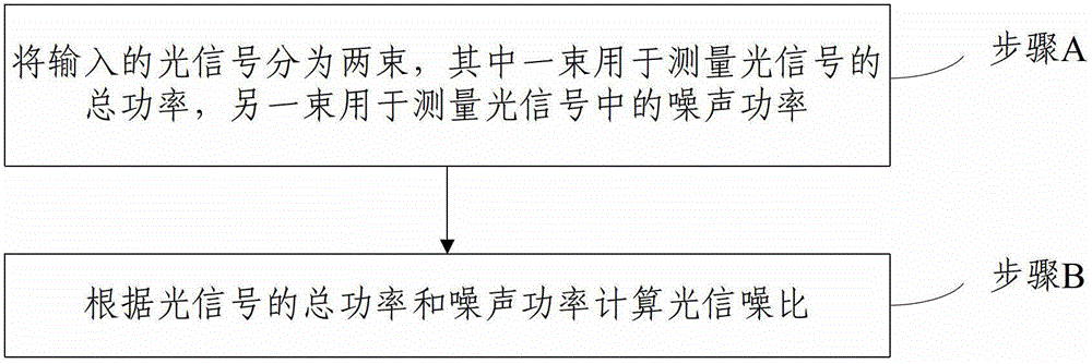
[0038] Embodiment 1 of the present invention provides an in-band optical signal-to-noise ratio detection method based on polarization interference, and the steps are as follows figure 1 As shown, it specifically includes the following steps:

[0039] Step A: Divide the input optical signal into two beams, one of which is used to measure the total power of the optical signal, and the other beam is used to measure the noise power in the optical signal.

[0040] Before dividing the input optical signal into two beams, filtering the optical signal is also included. The filtered optical signal passes through a coupler with a splitting ratio of γ to split the signal into two beams.

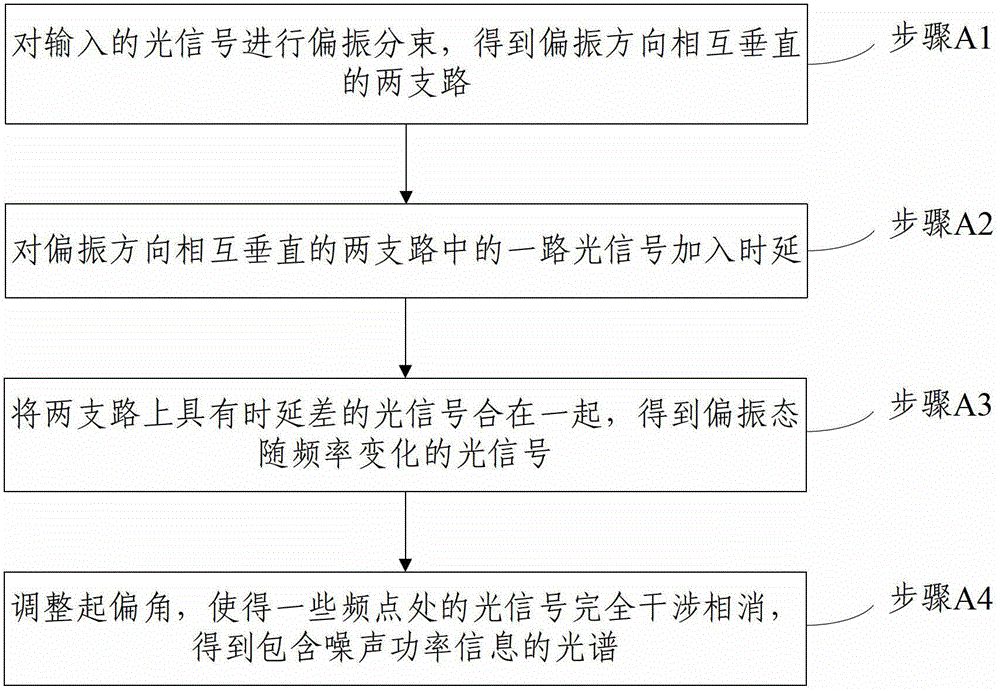
[0041] Step A measures the noise power in the optical signal. The specific process is as follows: figure 2 shown, including the following steps:

[0042] Step A1: performing polarization beam splitting on the optical signal used for measuring the noise power in the optical signal to obtain two branc...

Embodiment 2

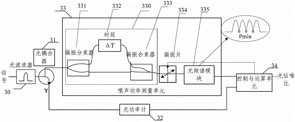
[0052] In order to achieve the above purpose, Embodiment 2 of the present invention also provides an in-band optical signal-to-noise ratio detection device based on polarization interference, the schematic diagram of which is shown in image 3 shown, including:

[0053] An optical coupler 31 , an optical power measurement unit 32 , a noise power measurement unit 33 and a control and calculation unit 34 .

[0054] An in-band optical signal-to-noise ratio detection device based on polarization interference provided in this embodiment further includes an optical filter 30, and the optical signal is filtered by the optical filter before entering the optical coupler.

[0055] The optical coupler 31 divides the input optical signal into two beams, one beam is input to the optical power measurement unit 32 , and the other beam is input to the noise power measurement unit 33 .


PUM


Abstract

The invention discloses a polarization interference-based in-band optical signal-to-noise ratio detection method and device. The method comprises the following steps of: dividing an input optical signal into two beams, of which one beam is used for measuring total power of the optical signal, and the other beam is used for measuring noise power in the optical signal; performing polarization beam splitting on the optical signal to obtain two branches which are perpendicular to each other in the polarization direction; adding time delay in one path of the two branches; combining the optical signals of the two branches together to obtain an optical signal with a polarization state varying along with frequency; adjusting a polarization angle of a polarizer to realize complete destructive interference of some frequency points so as to obtain an optical spectrum comprising noise power information; and calculating the optical signal-to-noise ratio according to the obtained total power of the optical signal and the noise power. According to the method and the device, the OSNR (Optical Signal to Noise Ratio) of the signal in a dynamic optical network and a high-speed optical fiber communication system can be detected, the detection range is 9-35 dB, the detection is not affected by the signal polarization state, optical fiber dispersion and polarization mode dispersion, the method and the device are transparent to a signal modulation format and a transmission rate, and the defects of the conventional OSNR detection method are overcome.

Description

technical field [0001] The invention relates to the technical field of optical communication, in particular to an in-band optical signal-to-noise ratio detection method and device based on polarization interference. Background technique [0002] OSNR (Optical signal to noise ratio) is one of the important parameters to measure the performance of optical signals in optical communication devices and networks. In the configuration, optimization, early warning, and daily inspection and maintenance of optical networks, OSNR detection is required. The current commercial OSNR detection modules are all based on the traditional out-of-band OSNR detection method, that is, the signal and noise power are measured at different frequency ranges (that is, the noise power is measured between the channels of the wavelength division multiplexing device). With the increasing spectrum utilization, the introduction of resettable optical add-drop multiplexers and other devices in dense wavelengt...

Claims


Application Information

Patent Timeline
Patent Type & Authority Applications(China)
IPC IPC(8): H04B10/077
Inventor 席丽霞彭文雨张晓光翁轩赵东鹤
Owner BEIJING UNIV OF POSTS & TELECOMM
Why Eureka
Try Eureka