Optical packet head extracting structure used for asynchronous optical packet switching network
An optical packet switching and optical packet technology, which is applied in data switching networks, selection devices for multiplexing systems, digital transmission systems, etc. Compared with the effect of simple structure
Inactive Publication Date: 2011-01-05
SOUTHEAST UNIV
View PDF0 Cites 0 Cited by
- Summary
- Abstract
- Description
- Claims
- Application Information
AI Technical Summary
Problems solved by technology
At present, there is a packet header extraction scheme using one or two semiconductor optical amplifier structures, but the switching ratio cannot reach a high level
Method used
View moreImage
Smart ImageViewing Examples
Examples
Embodiment Construction
Login to View More PUM
 Abstract
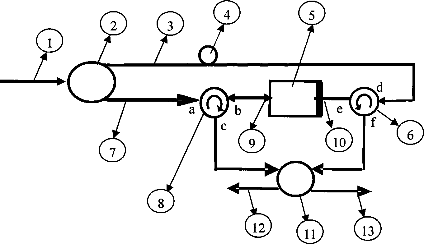
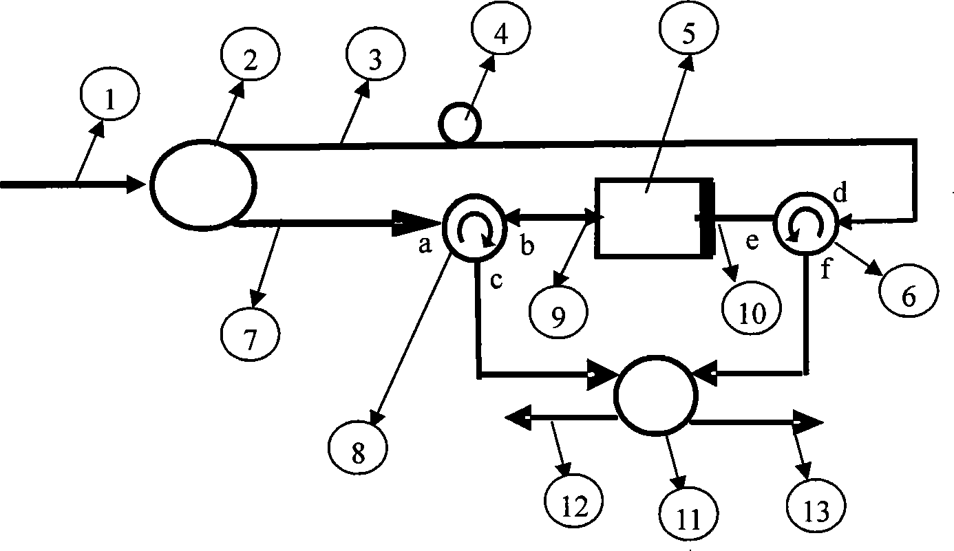
The invention discloses a retrieval structure of an optical packet head used in an exchange network of an asynchronous optical packet, which comprises a light splitter, a reflective semiconductor amplifier, a first circulator, a second circulator and a coupler; an input terminal of the light splitter is connected with packet input waveguide; a first output terminal of the light splitter is connected with a d port of the second circular through fiber delay lines, so that control signals which pass through the light splitter and are delayed are inputted to the reflective semiconductor amplifier; a second output terminal of the light splitter is connected with an a port of the first circulator; a b port of the first circulator is connected with the input / output terminal of the reflective semiconductor amplifier; a c port of the first circulator is connected with a first input terminal of the coupler; the input / output terminal of the reflective semiconductor amplifier is connected with ane port of the second circulator; an f port of the second circulator is connected with a second input terminal of the coupler. The retrieval structure of the optical packet head can increase on-off ratio of a system.
Description
Optical Packet Head Extraction Structure Used in Asynchronous Optical Packet Switching Network technical field The invention relates to an all-optical packet header extraction structure based on a reflective semiconductor optical amplifier (RSOA), in particular to an optical packet header extraction structure used in an asynchronous optical packet switching network. The invention can be used in high-speed optical transmission links to realize the extraction of the optical packet header (that is, the address code) in the optical packet. technical background Optical packet switching technology (TheopticalpacketswitchingOPS) is considered the most promising switching technology in the third-generation optical network. Due to the lack of optical RAM technology, all-optical routing has become an important bottleneck in the development of optical networks. But on the other hand, all-optical routers can be developed to realize switching and competition mechanisms in the waveleng...
Claims
Login to View More Application Information
Patent Timeline
 Patent Type & Authority Patents(China)
IPC IPC(8): H04Q11/00H04L12/56H04Q3/52
Inventor 孙小菡赵俊邵宗彪
Owner SOUTHEAST UNIV
Features
- R&D
- Intellectual Property
- Life Sciences
- Materials
- Tech Scout
- Unparalleled Data Quality
- Higher Quality Content
- 60% Fewer Hallucinations
Learn More Browse by: Latest US Patents, China's latest patents, Technical Efficacy Thesaurus, Application Domain, Technology Topic, Popular Technical Reports.
© 2025 PatSnap. All rights reserved.Legal|Privacy policy|Modern Slavery Act Transparency Statement|Sitemap|About US| Contact US: help@patsnap.com


