Strain relief and catheter provided with strain relief

A technology of strain relief and conduit, applied in the direction of conduit, electrical components, pipeline protection, etc., can solve problems such as excessive bending of strain relief parts, difficulty in selecting materials for strain relief parts, design of shape, and unsmooth transmission of operating force , to achieve the effect of improving operability

Active Publication Date: 2013-06-19
TERUMO KK
View PDF6 Cites 6 Cited by
  • Summary
  • Abstract
  • Description
  • Claims
  • Application Information

AI Technical Summary

Problems solved by technology

[0008] However, since the strain relief disclosed in Patent Document 1 and Patent Document 2 has a space between adjacent surrounding parts, the surrounding parts can be easily approached and separated from each other, and the strain relief as a whole may be overwhelmed. bending
Thus, if the strain relief bends excessively, there arises the problem of excessive loading being applied to the connection between the shaft and the hub when the catheter is manipulated.
In addition, there is a problem that the operating force (force for advancing and retreating and rotating) to the shaft cannot be smoothly transmitted.
[0009] Here, it is conceivable to avoid excessive bending by shortening the width of the space portion of the strain relief, but in this case, as the surrounding portions approach each other, the bending strength increases and the flexibility of the strain relief also changes.
Therefore, other problems such as difficulty in selecting the material of the strain relief member and designing the shape will arise.

Method used


Image

  • Strain relief and catheter provided with strain relief
  • Strain relief and catheter provided with strain relief
  • Strain relief and catheter provided with strain relief

Examples


Embodiment Construction

[0030] Hereinafter, the relationship between the strain relief of the present invention and a catheter having the strain relief will be described in detail with reference to the accompanying drawings by citing preferred embodiments.

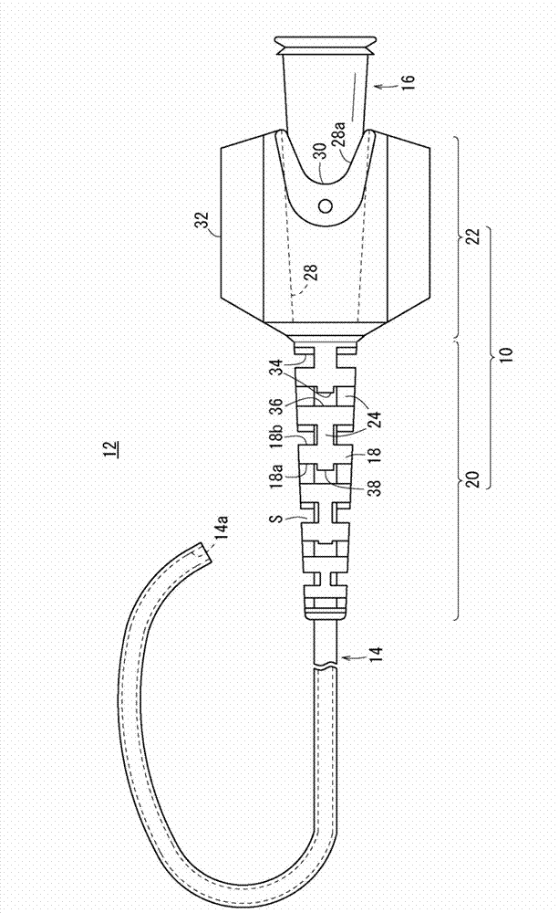
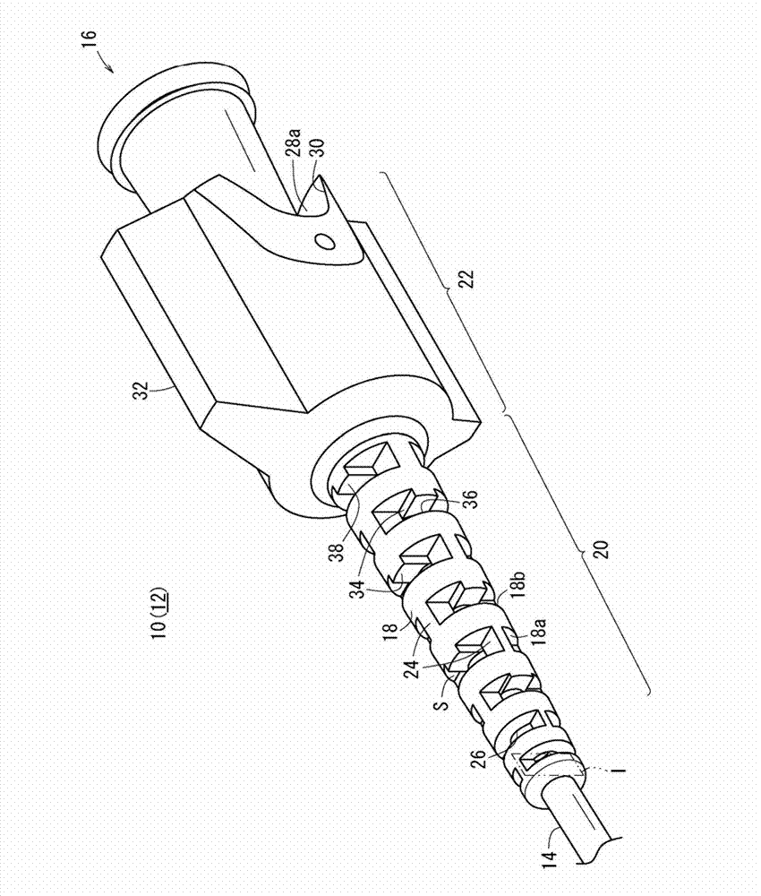
[0031] figure 1 It is a schematic side view showing the overall structure of the guide catheter 12 having the strain relief 10 of the present embodiment. Such as figure 1 As shown, the strain relief 10 is provided on a guide catheter 12 (hereinafter also simply referred to as the catheter 12 ) having a hollow vertically long shaft portion 14 (tube body). The guide catheter 12 is used, for example, in PTCA (Percutaneous Transluminal Coronary Angioplasty: Percutaneous Transluminal Coronary Angioplasty) for treating a narrowed portion of a blood vessel.

[0032] In this case, the catheter 12 is inserted into a meandering blood vessel (such as an aorta) with an insertion tool not shown, and the distal end thereof is delivered to a predetermined sit...


PUM


Abstract

It is an object of the present invention to prevent the connection part from excessively bending without changing the flexibility of a strain relief 10. The strain relief 10 has a plurality of enclosing parts 18 arranged in the axial direction and enclosing the axis, with a space part S formed between the adjacent enclosing parts 18 so that the strain relief 10 is freely bendable. The plurality of enclosing parts 18 are each provided at the distal end face thereof with a projection 34 projecting in the distal direction. The projection 34 comes into contact with the opposing enclosing part 18, whereby the degree of curvature when the strain relief 10 is curved is regulated.

Description

technical field [0001] The present invention relates to a strain relief for relieving a load applied to a connection portion of two members and a conduit having the strain relief. Background technique [0002] Generally, a catheter used in the medical field includes: a long shaft (tube body) having flexibility (flexibility); and a hub having rigidity connected (connected) to the proximal end of the shaft. Such a catheter tends to concentrate stress on the connecting portion between the shaft and the hub during use (handling), and the shaft may be bent and damaged (also called kink phenomenon). Therefore, the connection portion between the shaft portion and the hub is provided with a strain relief for increasing the strength of the connection portion. [0003] For example, Patent Document 1 discloses a strain relief having a plurality of strain relief coils surrounding a proximal peripheral surface of a catheter body. The plurality of surrounding parts are arranged in paral...

Claims


Application Information

Patent Timeline
Patent Type & Authority Applications(China)
IPC IPC(8): A61M25/00
CPCA61M25/0097A61M2025/0098F16L57/00H01R13/5841
Inventor 羽室皓太伊濑宽好
Owner TERUMO KK
Why Eureka
Try Eureka