Eureka AIR delivers breakthrough ideas for toughest innovation challenges, trusted by R&D personnel around the world.

Induction ring tracking device of rotary lathe

A technology of tracking device and induction ring, which is applied in the direction of feeding device, automatic control device, metal processing machinery parts, etc., can solve the problem of low milling flatness, inability to ensure the shape and dimensional accuracy of the milling surface, affecting the performance and life of the machine tool, etc. problem, to achieve the effect of ensuring shape and size accuracy and ingenious structure

Inactive Publication Date: 2013-06-19
WUXI HUALIAN PRECISION MACHINERY
View PDF5 Cites 0 Cited by
  • Summary
  • Abstract
  • Description
  • Claims
  • Application Information

AI Technical Summary

Problems solved by technology

Since the rotary machine tool is a large machine tool for milling super-large diameter workpieces, the small error detected on the ring close to the center position will be magnified many times when it reaches the end of the milling power head, resulting in low milling flatness, which cannot ensure the milling of the workpiece The shape and dimensional accuracy of the milling surface directly affect the performance and life of the machine tool

Method used


Image

  • Induction ring tracking device of rotary lathe
  • Induction ring tracking device of rotary lathe
  • Induction ring tracking device of rotary lathe

Examples


Embodiment Construction

[0014] Below the present invention will be further described in conjunction with the embodiment in the accompanying drawing:

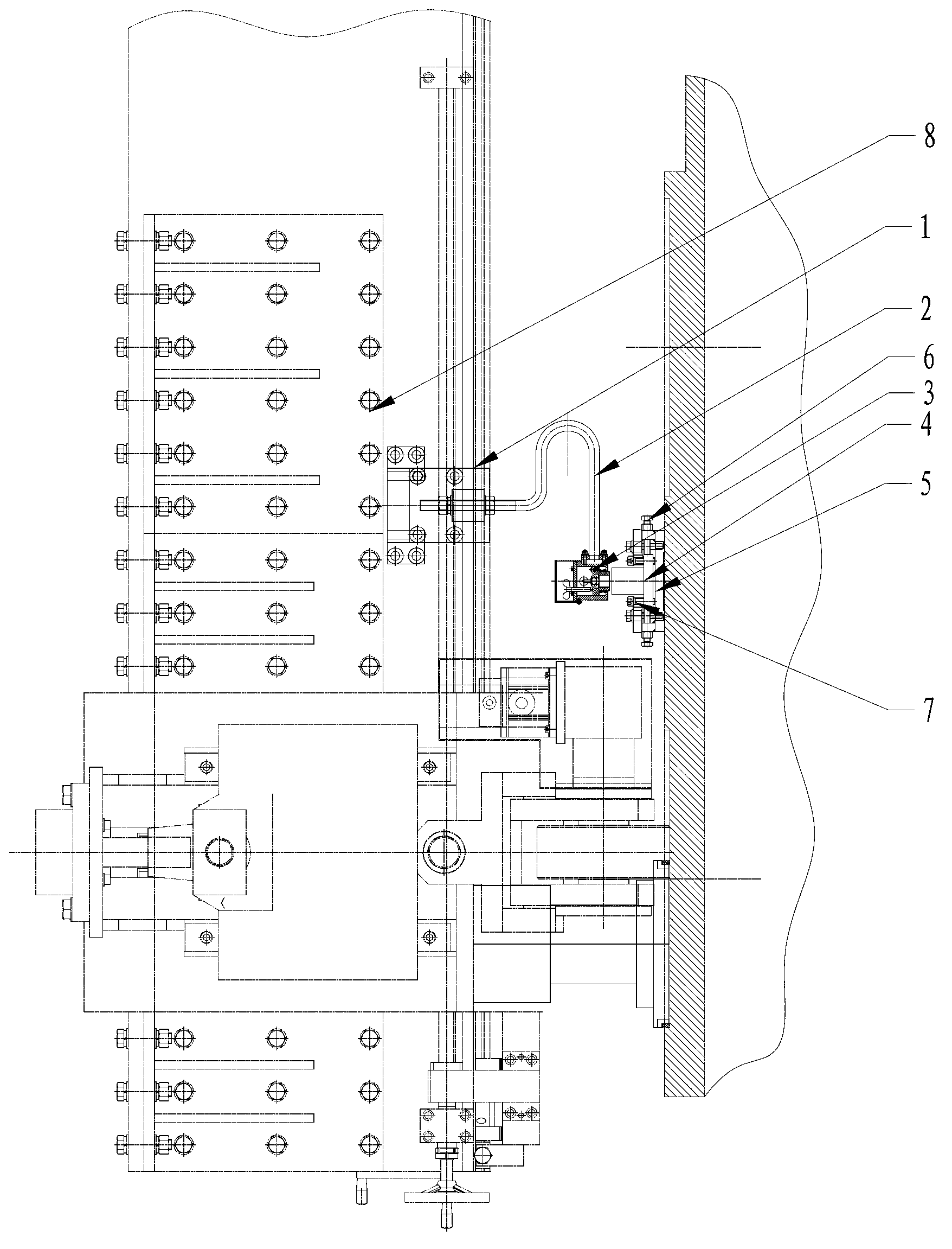
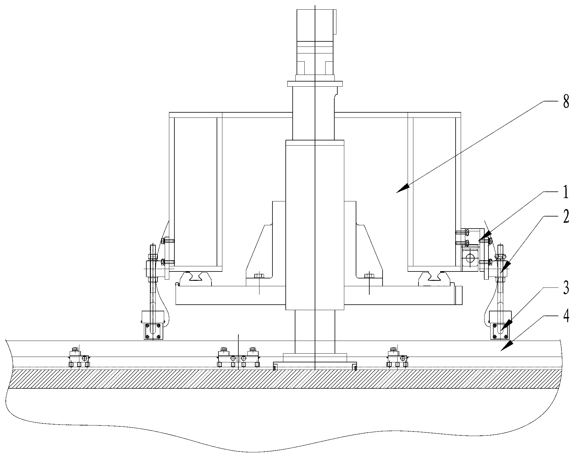
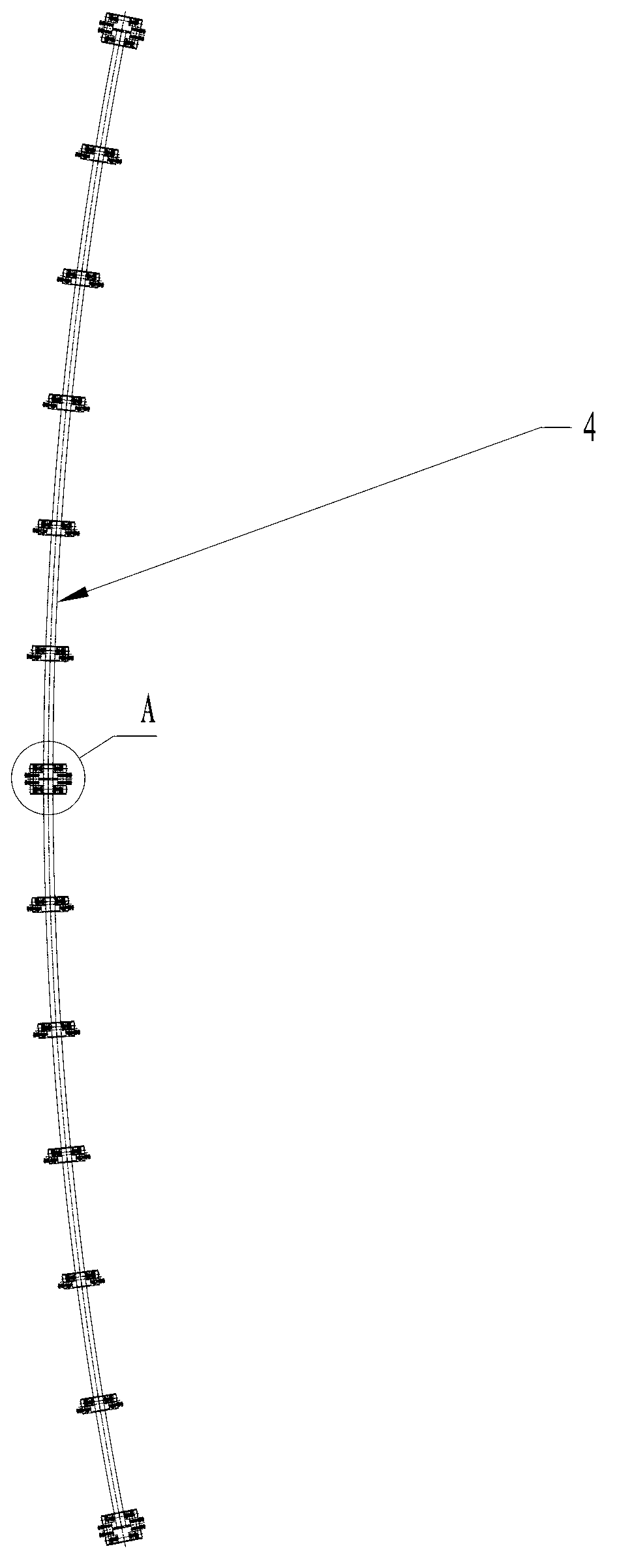
[0015] Such as Figure 1~4 As shown, the present invention mainly includes two bases 1 respectively fixed on both sides of the milling power head of the frame 8 , and each base 1 is connected with an eddy current sensor 3 through a sensor bracket 2 . An arc-shaped reference ring 4 is provided directly in front of the two eddy current sensors 3 .

[0016] Every other end of the reference ring 4 is connected with a backing plate 5, and a magnet is installed in each backing plate 5, and is adsorbed on the surface of the workpiece through the magnet. Each backing plate 5 is respectively connected with a first adjusting bolt 6 up and down, and the reference ring 4 is pressed vertically by the upper and lower first adjusting bolts 6 . Two second adjusting bolts 7 are connected to the side of each backing plate 5 , and the reference ring 4 is pressed horizo...


PUM


Abstract

The invention relates to an induction ring tracking device of a rotary lathe, in particular to a device used for guaranteeing the shape and size accuracy of a milling surface when a workpiece is milled, and belongs to the technical field of machining equipment. The induction ring tracking device of the rotary lathe comprises two bases respectively fixed at two sides of a milling power head of a machine frame, wherein each base is connected with an eddy-current sensor through a sensor support frame, an arc standard ring is arranged right in front of the two eddy-current sensors and is connected with cushion plates which are arranged at intervals, a magnet is arranged in each cushion plate, the upper portion and the lower portion of each cushion plate are respectively connected with a first adjustment bolt, and the standard ring is pressed vertically and tightly through the upper first adjustment bolt and the lower first adjustment bolt. A lateral surface of each cushion plate is connected with two second adjustment bolts, and the standard ring is pressed horizontally and tightly through the second adjustment bolts. The induction ring tracking device of the rotary lathe is ingenious, compact and reasonable in structure, and is capable of guaranteeing the shape and size accuracy of the milling surface when the workpiece is milled through tracking feedback of the eddy-current sensors.

Description

technical field [0001] The invention relates to an induction ring tracking device of a rotary machine tool, specifically used to ensure the shape and size accuracy of a milling surface when a workpiece is milled, and belongs to the technical field of mechanical processing equipment. Background technique [0002] There are high processing requirements for the surface of large disc workpieces. In order to ensure the processing flatness and roughness requirements of the workpiece surface, two sets of travel wheel mechanisms are respectively installed on both sides of the frame, and the travel wheel height adjustment mechanism and tracking detection device ensure the flatness of the workpiece surface. [0003] In the prior art, the induction tracking device is installed close to the rotating center frame. Since the rotary machine tool is a large-scale machine tool for milling super-large diameter workpieces, the small error detected on the ring close to the center position will...

Claims


Application Information

Patent Timeline
Patent Type & Authority Applications(China)
IPC IPC(8): B23Q15/12
Inventor 邵燕瑛周敏铨陆文彬周冰峰
Owner WUXI HUALIAN PRECISION MACHINERY
Why Eureka
Eureka Blog
Learn More