Power shift transmissions for construction machinery

A technology for power shifting and engineering machinery, which is applied in the field of shifting gearboxes and power shifting gearboxes. It can solve the problems of increased complexity and processing difficulty, increased manufacturing and maintenance costs, and many pairs of meshing pairs of transmission gears. Achieve the effects of improving power utilization, reducing manufacturing costs, and less parts involved in transmission

Active Publication Date: 2015-09-02
QINGDAO LOVOL EXCAVATOR
View PDF9 Cites 0 Cited by
  • Summary
  • Abstract
  • Description
  • Claims
  • Application Information

AI Technical Summary

Problems solved by technology

[0003] The above two kinds of transmission gears have many meshing pairs and many parts involved in the transmission. At the same time, both transmissions have eight shafts and six clutches, which will inevitably lead to a decrease in transmission efficiency, an increase in temperature rise, and increased wear and tear of parts, and manufacturing and maintenance costs. Increase
The two transmissions use a single-acting clutch, which increases the number of shafts and the number of mounting holes for the shafts on the box body, which increases the complexity and processing difficulty of the box, and increases the cost
[0004] The Chinese utility model patent with the patent application number "201120439772.7" discloses the "construction machinery hydraulic mechanical gearbox", in which the forward third gear and forward fifth gear transmission chains are too long, and the power is output through 8 pairs and 6 pairs of gears meshing respectively. Construction machinery, especially the reverse gear with high utilization rate of loaders also has 5 pairs of gears meshing to output power. Like the above two transmissions, the transmission chain is long, which will inevitably lead to a decrease in transmission efficiency, an increase in temperature rise, and increased wear of parts. Manufacturing and Increased maintenance costs

Method used


Image

  • Power shift transmissions for construction machinery

Examples


Embodiment Construction

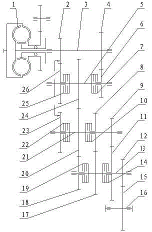
[0046] Examples such as figure 1 As shown, a power shift gearbox suitable for engineering machinery includes an input shaft 3 and an output shaft 16. One end of the input shaft 3 is connected to a torque converter 1. Between the input shaft 3 and the output shaft 16 The power transmission is carried out through three power transmission units. The three power transmission units include: the first intermediate shaft 5, which is connected to the input shaft 3; the third intermediate shaft 13, which is connected to the output shaft 16; the second intermediate shaft 21, which is connected to the input shaft 3 and the first intermediate shaft 5. The third intermediate shaft 13 is respectively connected by transmission.

[0047] The first fixed gear 2 and the second fixed gear 4 are fixedly connected to the input shaft, and the seventh fixed gear 15 is fixedly connected to the output shaft.

[0048] The first intermediate shaft 5 , the second intermediate shaft 21 and the third int...


PUM


Abstract

The invention discloses a power shift gear box applied to engineering machinery. The power shift gear box comprises an input shaft and an output shaft, and power transmission is conducted between the input shaft and the output shaft through three power transmission units. According to the power shift gear box, five transmission shafts are adopted, the total number of gears on each shaft is fourteen, the structure is simple, the pair number of the transmission gears is small, the number of parts participating into transmission is small, all forward gears output power through meshing of four pairs of gears, all backward gears output power through meshing of three pairs of gears, and therefore transmission efficiency is high. The number of the shafts is reduced, the structure of a box body is simple and manufacturing cost is reduced due to adoption of a double-acting clutch. Meanwhile, the gear box can adopt six forward gears and three backward gears, power utilization rate of an engine and acceleration performance of an automobile are improved, and the power shift gear box is suitable for being matched with a three-element torque converter which is high in transmission efficiency.

Description

technical field [0001] The invention relates to a shift gearbox, in particular to a power shift gearbox suitable for engineering machinery, and belongs to the technical field of engineering machinery. Background technique [0002] At present, the gearboxes used in construction machinery, such as loaders, graders, road rollers, and dump trucks, generally have two types: planetary type and fixed shaft type. The use of a planetary gearbox has a complex structure, high precision requirements, poor processing technology, and high manufacturing costs. Existing fixed-shaft gearboxes, for example, the Chinese invention patent with the patent application number "95196765.7" discloses "a multi-speed reversing transmission that can shift gears under load". Gear side effects output power, the first forward gear outputs power through six pairs of gears meshing, the remaining forward gears output power through four pairs of gears meshing, and the reverse gear outputs power through five p...

Claims


Application Information

Patent Timeline
Patent Type & Authority Patents(China)
IPC IPC(8): F16H3/093
CPCF16H3/093F16H2003/0818
Inventor 王金华贾策东孙长良徐奉刘世辉焦河阎秀芳
Owner QINGDAO LOVOL EXCAVATOR
Why Eureka
Try Eureka