Stereoscopic display device

A technology of stereoscopic display devices and screens, applied in projection devices, stereophotography, optics, etc., can solve problems such as inconvenience, and achieve the effect of reducing volume and cost

Active Publication Date: 2013-06-19
DELTA ELECTRONICS INC
View PDF3 Cites 10 Cited by
  • Summary
  • Abstract
  • Description
  • Claims
  • Application Information

AI Technical Summary

Benefits of technology

This patented technology allows for better utilization of space by combining different types of lights together without requiring more expensive equipment or bulky displays. It achieves this by creating an optical system where both eyes see things at once - one eye can focus on objects while other ones are blinds out.

Problems solved by technology

This patented technical problem addressed by this patents relates to improving the efficiency and cost effectiveness of producing autostereoscopes through liquid crystals or Plasmas Display technologies due to its limitations like slow response times and poor image quality. Current techniques involve creating smaller versions of these devices at different levels of detail level, which leads to increased costs compared to larger ones.

Method used


Image

  • Stereoscopic display device
  • Stereoscopic display device
  • Stereoscopic display device

Examples


Embodiment Construction

[0062] In order to make the description of the present invention more detailed and complete, reference may be made to the attached drawings and various embodiments described below, and the same numbers in the drawings represent the same or similar elements. On the other hand, well-known elements and steps have not been described in the embodiments in order to avoid unnecessarily limiting the invention.

[0063] In the description of the embodiments and the scope of the patent application, the description of "coupled with" can generally refer to an element being indirectly connected to another element through other elements, or an element is directly connected to the other element without passing through other elements. another element.

[0064] In the embodiments and the scope of the patent application, "a" and "the" can generally refer to a single or a plurality, unless there is a special limitation on the articles in the context.

[0065] As used herein, "about", "approxima...


PUM


Abstract

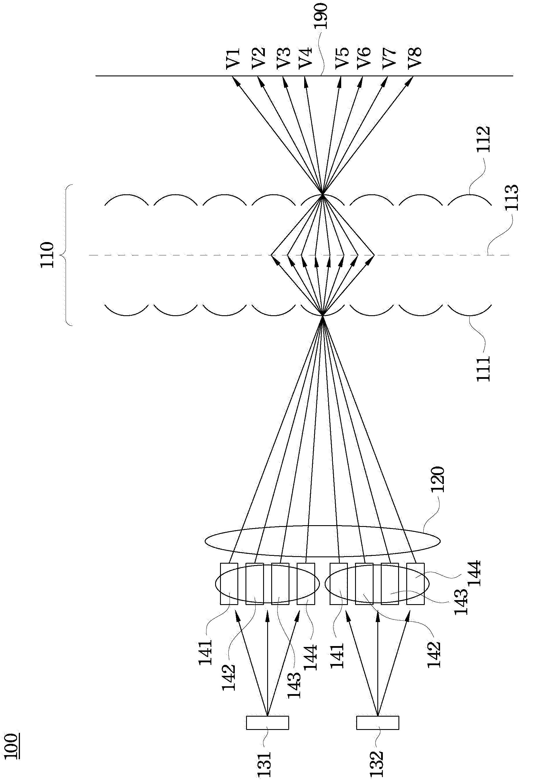
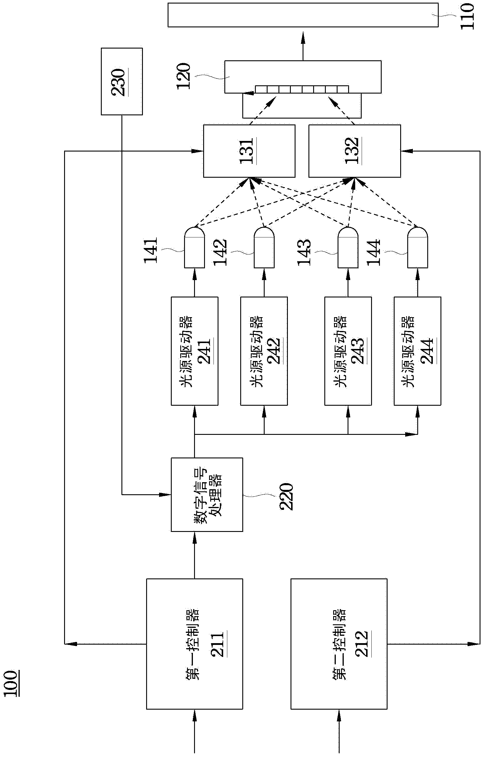
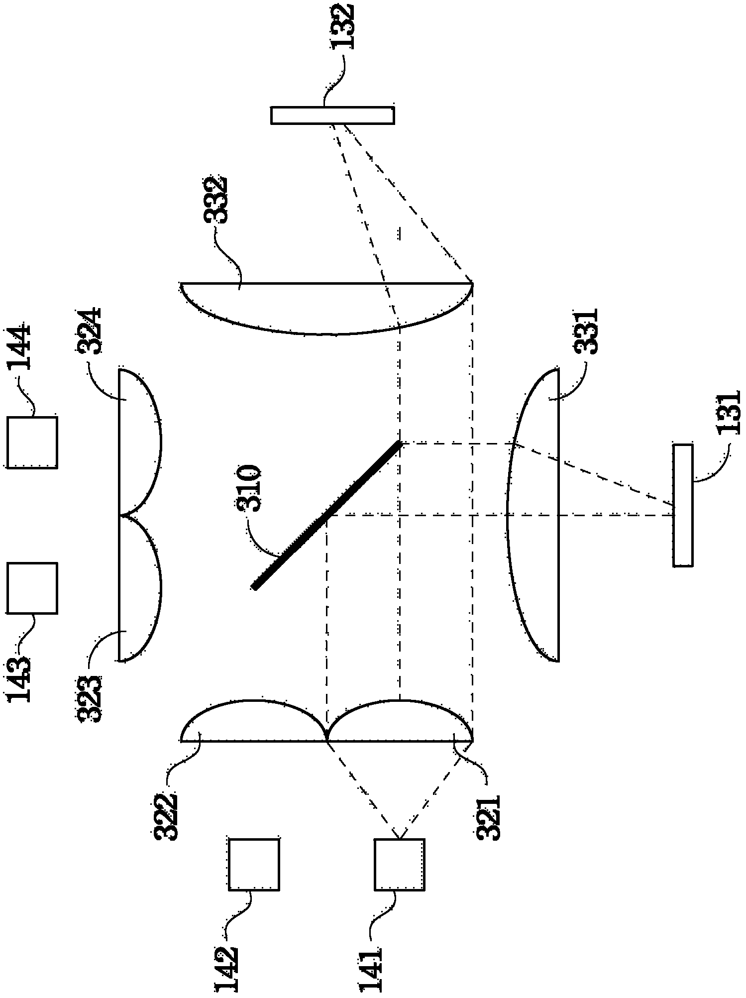
The invention discloses a stereoscopic display device which comprises a screen, a projection lens, two spatial light modulators, a plurality of light sources, an optical guidance system and a composite prism. The light sources are used for lighting by turns, when one of the light sources emits light rays, the optical guidance system is used for enabling the light rays to be divided into two parts which are then respectively guided to the two spatial light modulators, and the spatial light modulators are used for reflecting the light rays. The composite prism is used for enabling the light rays which are reflected by the two spatial light modulators to be conducted to the projection lens, and the projection lens aims at a screen on a light path to enable the screen to receive the light rays which are projected by the projection lens.

Description


Claims


Application Information

Patent Timeline
Owner DELTA ELECTRONICS INC
Why Eureka
Try Eureka