A process for producing nodular cast iron camshafts by clamping sand molds with iron molds

A ductile iron and camshaft technology, applied in the core, mold, mold composition and other directions, can solve the problems of low strength and elongation, unqualified metallographic structure, and high production cost, and achieve high strength and elongation. The metallographic structure is qualified and the cooling effect will not be too fast

Active Publication Date: 2021-12-21
JIANGXI TONGXIN MACHINERY MFG
View PDF14 Cites 0 Cited by
  • Summary
  • Abstract
  • Description
  • Claims
  • Application Information

AI Technical Summary

Problems solved by technology

[0002] The traditional nodular cast iron automobile camshaft casting process includes iron mold sand-covering process, shell mold buried steel shot process, shell mold process and wet clay sand process. The iron mold has a large investment and no flexibility, and cannot adapt to the production of small and medium batch products of various varieties. The casting residual stress is large, and stress relief annealing is required. The production cost is high. When the casting is cooled, the sand mold has no concession, and the product is easy to break or produce hidden cracks. If it is too thin, the heat absorption capacity of the iron mold is large, the molten iron cools quickly, it is easy to be cold shut, the shape is incomplete, the surface is easy to produce cementite, the metallographic structure is unqualified, it is difficult to process, the fluidity of the molten iron is poor, impurities are not easy to float, and slag inclusions are easy to occur , air holes, sand holes, cavity exhaust is not smooth, easy to produce air holes; the shell-type embedded steel shot process means that the shell mold is made and buried in the steel shot for pouring. The use of steel shot and the recovery system of this process require a lot of investment, and the process is complicated. The control is difficult, the labor intensity is high, and the operation is difficult. The overflowing molten iron is easy to stick to a large number of steel shots, the steel shot is worn out, the shell is thin, and the product is easy to bend. When the steel shot is separated from the molding sand, a large amount of dust is generated, causing air pollution; The shell molding process means that after the shell molding is made, it is poured directly on a flat surface. The shell molding is thick, the sand consumption is large, the riser is large, the process yield is low, the cooling is slow, the structure is coarse, the strength and elongation are low, and the molding sand is produced at high temperature. Phase change, easy cracking of the shell type, excessive length and size of the product, easy bending, poor shell rigidity, easy shrinkage of the product, poor air permeability of the sand mold, easy generation of pores, cold shut, large gas generation of the sand mold, causing air pollution; wet clay Sand process: The sand mold strength of this process is low, the length and dimension of the product are out of tolerance, easy to bend, the sand mold is easy to crack, the product is deformed, the shape is incomplete, the air permeability of the sand mold is poor, easy to produce air holes, cold shut, the local sand of the sand mold is easy to peel off, and sand holes are easy to occur , the surface is rough, sand mold positioning is difficult, easy to make mistakes and expand the box, the sand mold has a large heat absorption capacity, the molten iron cools quickly, it is easy to be cold, the shape is incomplete, the surface is easy to produce cementite, the metallographic structure is unqualified, difficult to process, molten iron Poor fluidity, impurities are not easy to float up, slag inclusions, air holes, sand holes are easy to occur, the technology is backward, and the product quality cannot be effectively controlled

Method used


Image

  • A process for producing nodular cast iron camshafts by clamping sand molds with iron molds

Examples


Embodiment Construction

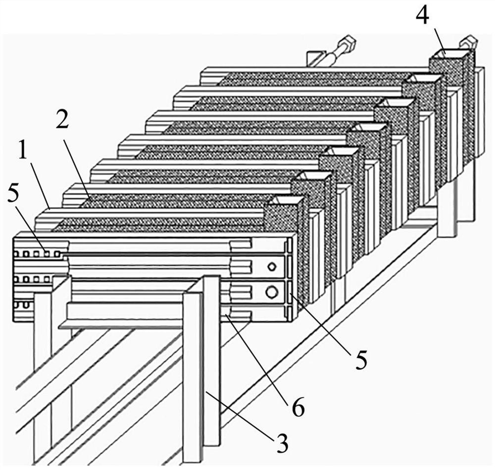
[0035] The process of producing a nodular cast iron camshaft by clamping sand molds with iron molds of the present invention will be further described in detail below in conjunction with the accompanying drawings.

[0036] The process of producing nodular cast iron camshafts by clamping sand molds with iron molds of the present invention uses gray cast iron to pour special iron molds to make special casting frames, places the special iron molds on the special casting frames, and uses double-sided horizontal sand injection molding machines to produce coatings Sand mold, place ceramic filter and glass fiber filter in the sand mold, bond the left and right sand molds to form a complete sand mold, place the sand molds one by one in the middle of the iron mold, and make the sand mold accurately embedded in the cavity of the iron mold. The molten iron after chemical treatment is poured into sand molds one by one, and the castings are separated. The specific production process include...


PUM


Abstract

The invention discloses a process for producing nodular cast iron camshafts by clamping sand molds with iron molds. Gray cast iron is used to cast special iron molds to make special pouring frames. To produce coated sand molds, place ceramic filters and glass fiber filter screens in the sand molds, bond the left and right sand molds to form a complete sand mold, place the sand molds one by one in the middle of the iron mold, and make the sand molds accurately embedded in the cavity of the iron mold, The molten iron after spheroidization treatment is poured into sand molds one by one, and the castings are separated. Using the process of the present invention, the production efficiency and process yield rate are greatly improved, the process cost is reduced, and product size, shrinkage, bending, shrinkage, and shrinkage are eliminated. The defect rate of slag inclusion, air hole, sand hole, cold shut, wrong box, and box expansion avoids unqualified metallographic structure, avoids unqualified mechanical properties, realizes energy saving and emission reduction, and reduces production costs.

Description

technical field [0001] The invention relates to a process for producing a nodular cast iron camshaft by clamping a sand mold with an iron mold, in particular to a casting process for a nodular cast iron camshaft of an automobile engine. Background technique [0002] The traditional nodular cast iron automobile camshaft casting process includes iron mold sand-covering process, shell mold buried steel shot process, shell mold process and wet clay sand process. The iron mold has a large investment and no flexibility, and cannot adapt to the production of small and medium batch products of various varieties. The casting residual stress is large, and stress relief annealing is required. The production cost is high. When the casting is cooled, the sand mold has no concession, and the product is easy to break or produce hidden cracks. If it is too thin, the heat absorption capacity of the iron mold is large, the molten iron cools quickly, it is easy to be cold shut, the shape is in...

Claims


Application Information

Patent Timeline
Patent Type & Authority Patents(China)
IPC IPC(8): B22C9/22B22C9/06B22C9/08B22D35/04
CPCB22C9/22B22D35/04B22C9/086B22C9/068
Inventor 杨启明乐文景余天
Owner JIANGXI TONGXIN MACHINERY MFG
Why Eureka
Try Eureka