Hydraulic driving rheostat

A varistor, hydraulic technology, applied in the direction of liquid resistors, resistance elements adjusted by short-circuiting different numbers of resistance elements, etc., can solve the problems of low sensitivity and high cost of all-electronic sensors, and achieve high sensitivity and low cost. Effect

Inactive Publication Date: 2013-06-19
XIAN WEIZHENG ELECTRONICS SCI & TECH
View PDF0 Cites 1 Cited by
  • Summary
  • Abstract
  • Description
  • Claims
  • Application Information

AI Technical Summary

Problems solved by technology

[0002] All-electronic sensors have the disadvantages of low sensitivity and high cost

Method used


Image

  • Hydraulic driving rheostat

Examples


Embodiment Construction

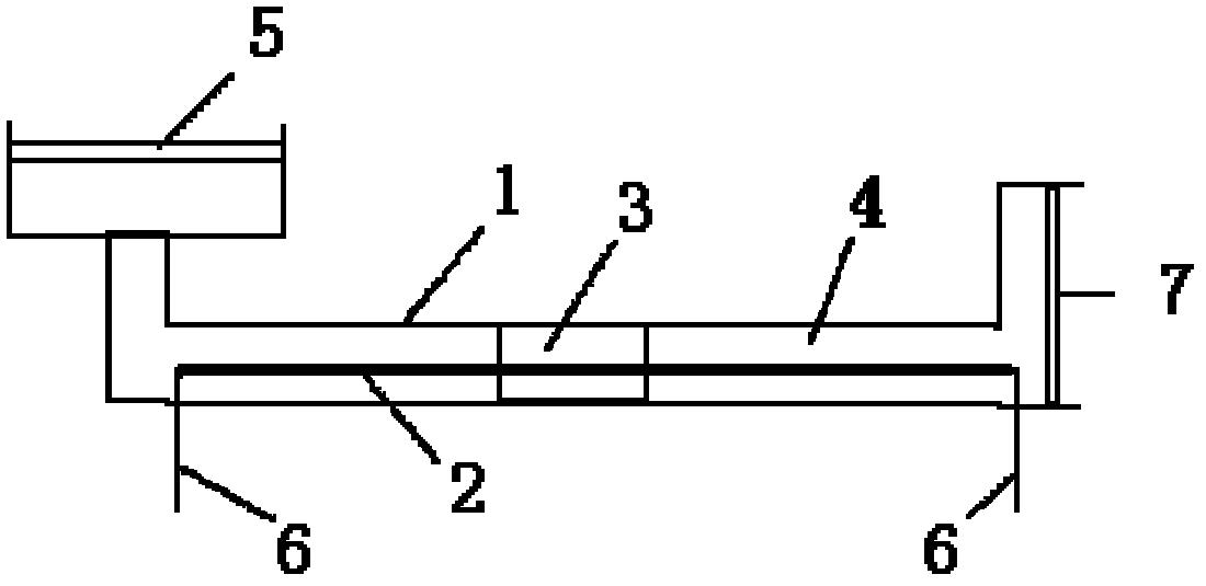
[0008] The present invention will be described in detail below in conjunction with the accompanying drawings.

[0009] With reference to the accompanying drawings, a hydraulic rheostat comprises a capillary 1, and the capillary 1 is provided with a resistance bar 2, a mercury column 3 and a medium liquid 4, the mercury column 3 is arranged in the middle of the resistance bar 2, and the two sides of the mercury column 3 For the medium liquid 4, one end of the thin tube 1 is provided with a first piston 5, and the other end is provided with a second piston 7, the first piston 5 and the second piston 7 turn the thin tube 1 into a closed hydraulic transmission device, and the resistance strip 2 communicates with the outside of the thin tube 1 through the lead wire 6.

[0010] Working principle of the present invention is:

[0011] The change of the first piston 5 and the second piston 7 is reflected by measuring the movement of the mercury column 3 on the resistance bar 2 to caus...


PUM


Abstract

A hydraulic driving rheostat comprises a thin tube. A resistor stripe, a mercury column and medium liquid are arranged in the thin tube, the mercury column is arranged in the middle of the resistor stripe, the medium liquid is arranged on two sides of the mercury column, a first piston is arranged at one end of the thin tube, a second piston is arranged at the other end of the thin tube, the first piston and the second piston change the thin tube into a closed hydraulic transmission device, the resistor stripe is communicated with the exterior of the thin tube, and changes of resistance valves at two ends of the resistor stripe are formed by measuring movement of the mercury column on the resistor stripe to cause short circuit of mercury on different portions of a resistor to reflect change situations of the first piston and the second piston. The hydraulic driving rheostat has the advantages of being high in flexibility and low in cost of construction.

Description

technical field [0001] The invention relates to a hydraulic rheostat. Background technique [0002] The all-electronic sensor has the disadvantages of low sensitivity and high cost. Contents of the invention [0003] In order to overcome the above-mentioned shortcomings of the prior art, the purpose of the present invention is to provide a hydraulic rheostat, which has the advantages of high sensitivity and low cost. [0004] In order to achieve the above object, the technical scheme that the present invention takes is: [0005] A hydraulic rheostat, comprising a thin tube 1, a resistance bar 2, a mercury column 3 and a medium liquid 4 are arranged in the thin tube 1, the mercury column 3 is arranged in the middle of the resistance bar 2, and the two sides of the mercury column 3 are medium liquid 4 , one end of the capillary 1 is provided with a first piston 5, and the other end is provided with a second piston 7, the first piston 5 and the second piston 7 turn the capi...

Claims


Application Information

Patent Timeline
Patent Type & Authority Applications(China)
IPC IPC(8): H01C10/02H01C10/06
Inventor 李佳徐晓东
Owner XIAN WEIZHENG ELECTRONICS SCI & TECH
Why Eureka
Try Eureka