
Switch

A switch and fixed magnet technology, applied in the field of switches, can solve the problems of affecting the operation feel, low operator comfort, life and circuit conduction effect.

Inactive Publication Date: 2013-06-19
KOSTAL SHANGHAI MANAGEMENT
View PDF5 Cites 2 Cited by
  • Summary
  • Abstract
  • Description
  • Claims
  • Application Information

AI Technical Summary

Problems solved by technology

[0005] Among the above switches, whether it is a rotary switch or a push-type switch, they are all contact switches, that is, the human-operated parts need to be in contact with other parts to control the conduction and disconnection of the circuit. The contact parts of the rotary switch and the push switch will have a certain degree of wear or elastic fatigue, which will not only have a certain impact on their own life and the conduction effect of the circuit, but more importantly, it will greatly affect the operating feel. Reduced operator comfort

Method used


Image

  • Switch
  • Switch
  • Switch

Examples


Embodiment Construction

[0027] The present invention provides a switch which further improves the operator's operating comfort.

[0028] The following will clearly and completely describe the technical solutions in the embodiments of the present invention with reference to the accompanying drawings in the embodiments of the present invention. Obviously, the described embodiments are only some, not all, embodiments of the present invention. Based on the embodiments of the present invention, all other embodiments obtained by persons of ordinary skill in the art without making creative efforts belong to the protection scope of the present invention.

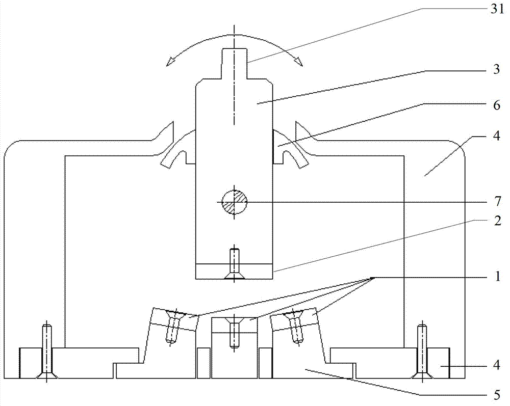
[0029] In the switch provided by the present invention, the number of fixed magnets can be one or multiple. Now take the setting of three fixed magnets as an example, and describe the switch in detail in conjunction with the accompanying drawings. It is not possible to set the three fixed magnets The method is understood as an absolute limitation on the sc...


PUM


Abstract

The invention provides a switch which comprises a fixed magnet and a movable magnet, wherein the movable magnet and the fixed magnet can be positioned under the action of magnetic force. Operation hand feeling is embodied by the aid of the magnetic force between the movable magnet and the fixed magnet of the switch, and a contact operation mode of a traditional touch switch is replaced. As the movable magnet and the fixed magnet are in non-contact induction, mutual abrasion of parts is avoided, the operation handle feeling of operators cannot be affectedin long-time repeated use, and operation comfort is further improved.

Description

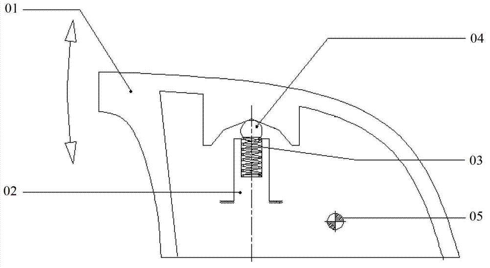
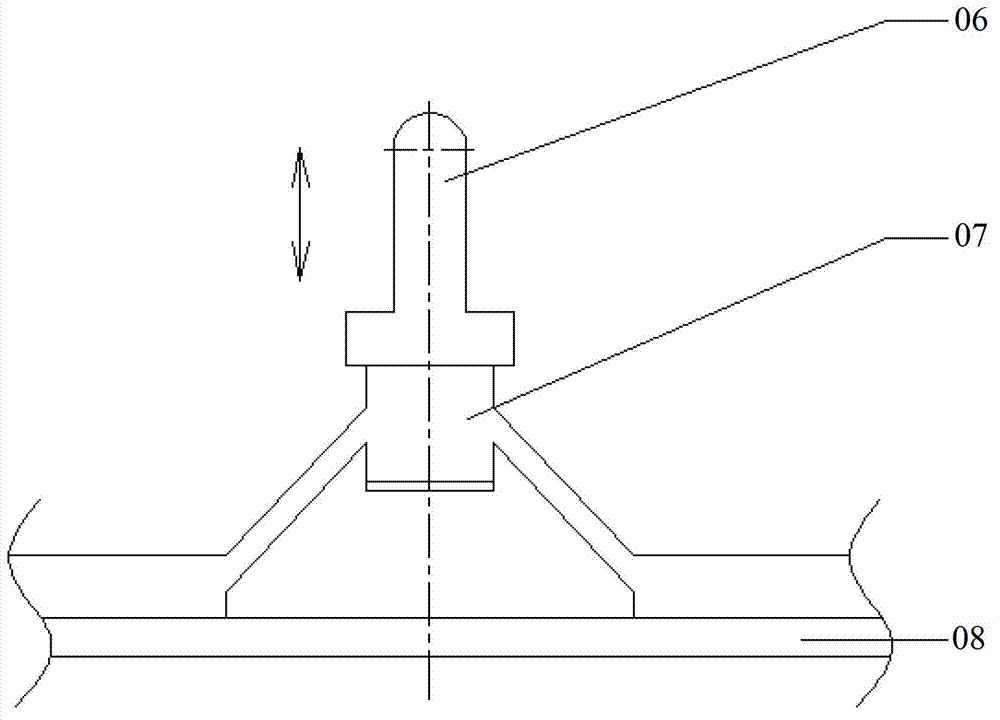
technical field [0001] The present invention relates to the technical field of electrical equipment, and more specifically, to a switch. Background technique [0002] At present, most of the switches installed in the circuit on the market are rotary or push-type. Among them, the rotary switches include car power window switches, electronic handbrake switches, etc.; the push-type switches include car steering wheel audio switches, air-conditioning adjustment switches, etc. [0003] Such as figure 1 As shown, it is a schematic structural diagram of a rotary switch, which includes a rotary body 01, a fixed body 02, an elastic component 03, and a friction component 04 (steel balls or plastic parts), wherein the rotary body 01 is manually operated The component rotates around the rotation center 05, and the rotation direction is shown by the arrow in the figure. The friction component 04 is arranged on the fixed body 02 through the elastic component 03, and is in contact with th...

Claims


Application Information

Patent Timeline
IPC IPC(8): H01H3/02
Inventor 吴剑伟石林荣林砥屹李良军
Owner KOSTAL SHANGHAI MANAGEMENT
Learn More