
Operation structure of automobile seat height adjustor

A height adjuster, car seat technology, applied in the direction of movable seats, etc., can solve the problems of poor operating feel, poor lateral stiffness, and lateral shaking, so as to avoid loosening and abnormal noise, good support strength, and avoid sideways Shaking effect

Active Publication Date: 2014-10-29
CHONGQING CHANGAN AUTOMOBILE CO LTD
View PDF6 Cites 1 Cited by
  • Summary
  • Abstract
  • Description
  • Claims
  • Application Information

AI Technical Summary

Problems solved by technology

The current operating structure of the height adjuster used to adjust the height of the car seat is: the operating handle bracket is directly connected to the central axis of the height adjuster. If the operating handle bracket is short, the operating force is large; if the operating handle bracket is lengthened, although the operation The force is reduced, but there are problems such as too long cantilever, poor lateral rigidity, prone to lateral shaking, deformation, and poor operating feel

Method used


Image

  • Operation structure of automobile seat height adjustor

Examples


Embodiment 1

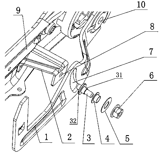
[0019] Example 1: The operating structure of the car seat height adjuster includes an operating handle bracket 1 connected to the central axis 10 of the height adjuster, and an inverted U-shaped lateral side welded on the seat frame 9 to support the operating handle bracket 1. The support plate 2, the limit assembly connected with the lateral support plate 2 and used to limit the rotation stroke and lateral sliding of the operating handle bracket 1; the limit assembly includes a connecting shaft and a nut, and the connecting shaft is in clearance fit with the waist-shaped hole 7, One end of the connecting shaft is riveted on the other side of the lateral support plate 2, and the other end of the connecting shaft is locked on the outside of the operating handle bracket 1 by a nut.

[0020] The assembly process is as follows: first, one side of the lateral support plate 2 is welded on the seat frame 9; secondly, one end of the connecting shaft is riveted to the other side of th...

Embodiment 2

[0022] Example 2: Such as figure 1 The operating structure of the car seat height adjuster shown includes an operating handle bracket 1 connected to the central axis 10 of the height adjuster, and an inverted U-shaped structure welded on the seat frame 9 to support the operating handle bracket 1. The lateral support plate 2, the limit assembly connected with the lateral support plate 2 and used to limit the rotation stroke and lateral sliding of the operating handle bracket 1; the limit assembly includes a limit shaft 3 with two steps in the middle, T Shaped plastic bushing 4, plastic gasket 5 and connecting nut 6, on the other side of the lateral support plate 2, there is a riveting hole 8, and one end of the limit shaft 3 is riveted to the lateral support plate 2 through the riveting hole 8 On this side of the operating handle bracket 1, there is a waist-shaped hole 7 with the same arc center as the rotation center of the operating handle bracket 1, and the T-shaped plasti...


PUM


Abstract

The invention discloses an operation structure of an automobile seat height adjustor. The operation structure comprises a operation handle support, a side-direction supporting plate and a limiting assembly, wherein the operation handle support is connected to a central shaft of the height adjustor, the side-direction supporting plate is welded to a seat skeleton and used for supporting the operation handle support, and the limiting assembly is connected with the side-direction supporting plate and used for limiting the rotation stroke of the operation handle support and side-direction sliding. A kidney-shaped hole is formed in the operation handle support, the center of the circular arc of the kidney-shaped hole is same as the rotation center of the operation handle support, the limiting assembly is in clearance fit with the kidney-shaped hole, and the operation handle support can slide around the limiting assembly through the kidney-shaped hole. According to the operation structure, the side-direction rigidity of the operation handle support can be improved, it is avoided that because the operation handle support is lengthened, side-direction shaking and deforming occur, and operation comfort is improved.

Description

technical field [0001] The invention relates to the technical field of car seats, in particular to an operating structure of a car seat height adjuster. Background technique [0002] In order to improve the comfort and safety of the occupants, car seats generally have basic adjustment functions such as height adjustment, front and rear adjustment, and backrest adjustment. With the development of the domestic automobile market and consumers' increasingly mature understanding of automobiles, the requirements for the adjustment and operation quality of automobile seats are getting higher and higher. issues of greater concern. At present, the operating structure of the height adjuster used to adjust the height of the car seat is: the operating handle bracket is directly connected to the central axis of the height adjuster. If the operating handle bracket is short, the operating force will be large; The force is reduced, but there are problems such as too long cantilever, poor...

Claims


Application Information

Patent Timeline
Patent Type & Authority Applications(China)
IPC IPC(8): B60N2/16
Inventor 岳路长李懿周川袁秀蓉钟贤彬
Owner CHONGQING CHANGAN AUTOMOBILE CO LTD
Learn More