Knob

A knob and rotation center technology, applied in the field of knobs, can solve problems such as poor contact, wear of contact pieces, short life, etc., to achieve the effects of ensuring performance stability, reducing positioning requirements, and prolonging service life

Inactive Publication Date: 2012-10-10
HUIZHOU DESAY SV AUTOMOTIVE
View PDF4 Cites 10 Cited by
  • Summary
  • Abstract
  • Description
  • Claims
  • Application Information

AI Technical Summary

Problems solved by technology

The main defect of this type of knob is: the carbon film of the potentiometer or the contact piece of the encoder and the paddle switch is easy to wear due to the friction between the contact parts, resu

Method used


Image

  • Knob
  • Knob

Examples


Example Embodiment

[0011] The knob of the present invention will be further described in detail below in conjunction with specific embodiments and accompanying drawings.

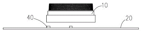
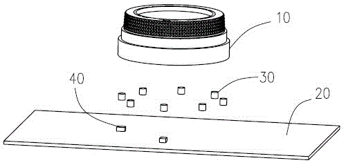
[0012] like Figure 1 to Figure 2 As shown, in one embodiment, the knob of the present invention mainly includes an operation cap (hereinafter referred to as the cap) 10, a circuit board 20 behind the cap, a plurality of magnetic particles 30 fixed inside the cap, and a plurality of magnetic particles fixed on the circuit board. (two or more) magnetic sensors 40 . When the cap 10 is operated in which the knob is turned, the cap 10 is not in contact with the circuit board 20 .

[0013] The cap 10 is used as an operating part of the knob, and is generally rotationally symmetrical, and may be hemispherical, cylindrical or ring-shaped. In this embodiment, the cap 10 is ring-shaped. The cap 10 is usually movably fixed on the casing of the device, and the circuit board 20 is fixed inside the casing of the device.

[0014] A plur...


PUM


Abstract

The invention relates to a knob, which comprises an operation cap, a circuit board arranged behind the cap, a plurality of magnetic particles, and a plurality of magnetic sensors, wherein the magnetic particles basically adopt a rotating center of the operation cap as a circular center and are uniformly and fixedly arranged on an inner side of the operation cap; and the magnetic sensors also basically adopt the rotating center of the operation cap as a circular center and are arranged on the circuit board. When the operation cap is rotated, the magnetic particles are rotated along with the rotation of the operation cap; and the magnetic sensors are used for sensing magnetic field variation generated when the magnetic particles are rotated. Physical independence, i.e. non-contact is realized between an operation structure of the knob and an operation signal receiving device; the defect of physical abrasion caused by physical contact can be overcome; and the service life of the knob is prolonged, and the performance stability of industry is ensured. In addition, the knob is flexible, the operation feel cannot be affected by the receiving device, the positioning requirement of product assembly is reduced, and the productivity is improved.

Description

technical field [0001] The present invention relates to a knob, in particular to a non-contact controller knob. Background technique [0002] Many controllers, such as car air conditioner controllers, are provided with knobs, and certain control functions can be realized by rotating the knobs. The existing knobs are all in contact with the main circuit board of the controller, including two modes of continuous contact and discontinuous contact. These two contact methods all rely on the "potentiometer" type, "encoder" type or "paddle switch" type core components. The main defect of this type of knob is: the carbon film of the potentiometer or the contact piece of the encoder and the paddle switch is easy to wear due to the friction between the contact parts, resulting in unstable control signals or poor contact, which leads to poor work of the controller. Stable and short-lived. Such defects are more likely to appear especially when the car vibrates during driving. Conte...

Claims


Application Information

Patent Timeline
IPC IPC(8): G05G1/10
Inventor 郭锦兴张华彬孙思铭
Owner HUIZHOU DESAY SV AUTOMOTIVE
Why Eureka
Try Eureka