Automobile radiator mounting structure

An automobile radiator and installation structure technology, which is applied to the arrangement of the cooling combination of the power unit, power unit, vehicle components, etc., can solve problems such as local cracks in the bracket, engine temperature rise, driving safety accidents, etc., to improve work stability performance, prevent mutual wear, and improve service life

Inactive Publication Date: 2014-10-08
成都万顺达模具零件有限公司
View PDF7 Cites 2 Cited by
  • Summary
  • Abstract
  • Description
  • Claims
  • Application Information

AI Technical Summary

Problems solved by technology

[0003] The radiator is installed inside the car, and is usually fixedly connected to the engine compartment through an ordinary bracket, but the ordinary bracket is easy to be rusted in a high-humidity environment near the engine, especially when the car is driving in a bumpy area. Ordinary brackets have partial cracks or direct fractures due to shaking, which will cause the connection between the radiator and the engine to break, causing the engine temperature to rise sharply and causing driving safety accidents

Method used


Image

  • Automobile radiator mounting structure
  • Automobile radiator mounting structure

Examples


Embodiment 1

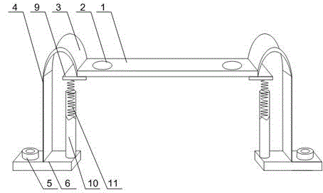
[0021] Such as figure 1 with figure 2 As shown, a kind of automobile radiator installation structure of the present invention, comprises fixed plate 1 and the support plate 4 that is arranged on the two ends of fixed plate 1, has mounting hole 2 on fixed plate 1, also includes elastic connector 3, and described elastic The connector 3 is U-shaped, and the opening of the U-shaped elastic connector 3 is downward. One end of the elastic connector 3 is connected to the end of the fixed plate 1, and the other end of the elastic connector 3 is connected to the upper end of the support plate 4. connection, the lower end of the support plate 4 is connected with a mount 6, and one end of the mount 6 has a fixing hole 7; it also includes a shock absorber 10 and a spring 11 placed in the shock absorber 10, and the shock absorber 10 is fixed On the mounting seat 5 , a connecting block 9 is installed at the bottom of the fixing plate 1 , and the two ends of the spring 11 are respectively...

Embodiment 2

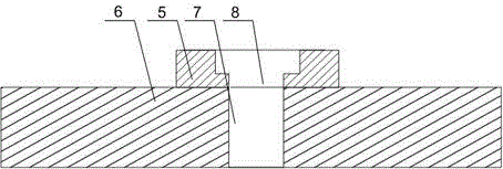
[0025] Such as figure 2 As shown, an automobile radiator installation structure of the present invention, an annular protrusion 5 is installed on the fixing hole 7, and the bottom of the annular protrusion 5 is provided with a through hole 8 communicating with the fixing hole 7, and the through hole 8 Isometric with fixing hole 7. The environment in the engine compartment is special, and sundries such as high temperature and oil stains are easy to accumulate, which has a great impact on the fixed connection of the mounting seat 6. Usually, the bolts are prone to corrosion and wire stripping. 5, and the bottom of the annular protrusion 5 is provided with a through hole 8 of equal diameter that communicates with the fixing hole 7, the screw rod passes through the through hole 8 and the fixing hole 7 to connect with the bottom of the machine compartment in turn, and the screw cover is fixed and protected in the ring In the groove, to prevent the screw and screw cover from being...


PUM


Abstract

The invention discloses an automobile radiator mounting structure. The automobile radiator mounting structure comprises a fixing plate and supporting plates arranged at the two ends of the fixing plate. Elastic connecting pieces are of a U shape, and openings of the U-shaped elastic connecting pieces face downwards. One end of each elastic connecting piece is connected with the end of the fixing plate. The other end of each elastic connecting piece is connected with the upper end of the corresponding supporting plate. The lower end of each supporting plate is connected with a mounting base. A damper cylinder is fixed to each mounting base. The bottom of the fixing plate is provided with connecting blocks. The two ends of each spring are connected with the corresponding damper cylinder and the bottom of the corresponding connecting block. In the long-term using process, the elastic connecting pieces can be worn to some extent and need to be replaced regularly; the connecting blocks mounted at the bottom of the fixing plate are matched with the springs, so that at the moment when stress of a radiator acts on the fixing plate, most of the sudden stress generated by the fixing plate is offset to reduce the workload of the elastic connecting pieces, and consequently the service life of the elastic connecting pieces is further prolonged.

Description

technical field [0001] The invention relates to an auxiliary tool, in particular to an automobile radiator installation structure. Background technique [0002] The heat transfer components of the car cooling system mainly include radiators, air-to-air coolers, fans and air guides, and controllable fan clutches. Vehicles used in cold climates often also have winter cowls or shutters in front of the cooling system; vehicles with automatic transmissions also have transmission radiators. In addition, this cooling system is equipped with special coolant lines. When the vehicle is running in a mild and cold environment, the heat exchange components of the cooling system control the temperature of the coolant, the air in the intake pipes and the transmission oil within an appropriate range; when the vehicle is running in a very hot environment, they In addition, the temperature of the above-mentioned medium is maintained below the specified level. Under the action of the engine...

Claims


Application Information

Patent Timeline
Patent Type & Authority Applications(China)
IPC IPC(8): B60K11/04
Inventor 贺方林张先强杨清明
Owner 成都万顺达模具零件有限公司
Why Eureka
Try Eureka