Battery management system and corresponding electronic system

A battery management system and electronic system technology, applied in battery circuit devices, current collectors, electric vehicles, etc., can solve the problems of reducing system energy efficiency, damaging the battery management system, large current surge impact, etc., achieving high reliability, Simple structure and low cost

Active Publication Date: 2015-04-15
DONGGUAN POWERWISE TECH CO LTD
View PDF1 Cites 0 Cited by
  • Summary
  • Abstract
  • Description
  • Claims
  • Application Information

AI Technical Summary

Problems solved by technology

However, the disadvantage of the above solution is that when a large current passes through a large current control device, heat loss will be generated, which will reduce the energy efficiency of the entire system
At the same time, in the process of turning on or turning off the high current, a surge of high current will be generated, which will damage the battery management system
In addition, the high current control device itself frequently turns on or off the high current, which will reduce its life

Method used


Image

  • Battery management system and corresponding electronic system

Examples


Embodiment Construction

[0018] In order to further explain the technical means and effects of the present invention to achieve the intended purpose of the invention, the specific implementation methods, methods, steps, The structure, characteristics and effects thereof are described in detail as follows. The aforementioned and other technical contents, features and effects of the present invention will be clearly presented in the following detailed description of preferred embodiments with reference to the drawings. Through the description of specific implementation methods, the technical means and effects of the present invention to achieve the intended purpose can be understood more deeply and specifically, but the attached drawings are only for reference and description, and are not used to explain the present invention limit.

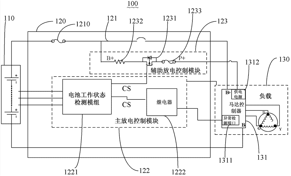
[0019] figure 1 It is a schematic diagram of an electronic system disclosed in a preferred embodiment of the present invention. Such as figure 1 As shown, the electron...


PUM


Abstract

A battery management system is used for determining whether a battery device is enabled to supply power for a load. The battery management system comprises a discharging return circuit and a main discharging control module. The discharging return circuit is used for achieving connection between the battery device and the load. The main discharging control module is used for detecting the state of the battery device and producing corresponding control signals when the battery device is in an abnormal state, so that the load is forced to stop working and then the load is forced to cut off the electrical connection between the battery device and the load in an initiative mode. Therefore, the battery management system is simple in structure, low in cost and high in reliability due to the adoption of dual protection of the main discharging control module and an auxiliary discharging control module.

Description

technical field [0001] The present invention relates to the technical field of batteries, in particular to a battery management system and a corresponding electronic system. Background technique [0002] In the process of battery application, because loads, such as high-power electric motorcycles, etc., usually require high current to work, therefore, in the process of turning on and off the high current, it will produce current shock and large heat consumption , In addition, it will also damage the large current control device. [0003] The current main solution is to use large relays or contactors to directly turn on or off large currents. However, the disadvantage of the above solution is that when a large current passes through a large current control device, heat loss will be generated, which will reduce the energy efficiency of the entire system. At the same time, during the turn-on or turn-off process of a large current, a surge impact of a large current will be gen...

Claims


Application Information

Patent Timeline
Patent Type & Authority Patents(China)
IPC IPC(8): H02J7/00H02H7/18
Inventor 葛伟国
Owner DONGGUAN POWERWISE TECH CO LTD
Why Eureka
Try Eureka