Pouring method for motor stator connector box

A generator stator and pouring method technology, applied in the direction of manufacturing motor generators, electromechanical devices, electrical components, etc., can solve the problems of heavy workload, low work efficiency, long time, etc., achieve convenient operation, save maintenance costs, reduce The effect of maintenance time

Active Publication Date: 2015-04-29
STATE GRID CORP OF CHINA +1
View PDF2 Cites 0 Cited by
  • Summary
  • Abstract
  • Description
  • Claims
  • Application Information

AI Technical Summary

Problems solved by technology

This method has a large workload, a long time and low work efficiency

Method used


Image

  • Pouring method for motor stator connector box
  • Pouring method for motor stator connector box

Examples


Embodiment Construction

[0024] The present invention is described in detail below with reference to accompanying drawing and embodiment:

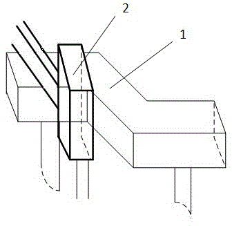
[0025] attached figure 1 As can be seen from 4, 1. A generator stator joint box pouring method comprises the steps:

[0026] 1) Put the Z-shaped insulation box into the drying oven, set the temperature of the drying oven to 80 degrees, and dry for two hours;

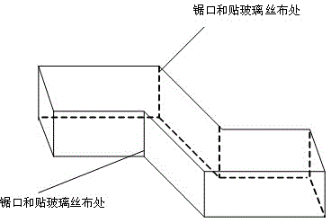
[0027] 2) Take the Z-shaped insulation box out of the drying oven, saw off the top cover of the insulation box; remove 3cm from the left and right ends of the sawn top cover; saw off the insulation box, and divide the insulation box into left and right parts, Wipe all parts of the sawn insulation box with alcohol;

[0028] 3) Use toluene or absolute ethanol to clean the joints and various parts of the insulation box;

[0029] 4) Install the Z-shaped insulation box, connect the insulation boxes sawn left and right into one; put the top cover of the sawn insulation box into the insulation box, use it as the...


PUM


Abstract

The invention relates to a pouring method for a motor stator connector box. The method comprises sawing a Z type insulation box into two halves, fixing, filling adhesion and recovering mechanical strength and the insulation strength of the insulation box. The pouring method for the motor stator connector box is simple in process and convenient to operate, reduces overhaul work load, reduces maintenance time, and saves maintenance cost.

Description

technical field [0001] The invention relates to a method for installing and processing a generator stator joint box, in particular to a pouring method for a generator stator joint box. [0002] The technical field of improving the installation and processing of the generator stator joint box is especially used for the installation of the insulation box with the wire bar jumpering the busbar above the Z-type insulation box of the generator, and the restoration of the mechanical strength and the insulation strength. Background technique [0003] During the maintenance process of the generator, various insulation boxes need to be replaced. There are wire bars on the top of the Z-type insulation box of the generator to bridge the busbars, and the gap between them is as small as 2-3cm. It is troublesome to replace in this environment. The prior art is: the wire bar jumper busbar joints above the Z-shaped insulating box are melted, and then the wire bar jumper busbar joints above ...

Claims


Application Information

Patent Timeline
Patent Type & Authority Patents(China)
IPC IPC(8): H02K15/00B29C39/02
Inventor 赵海春
Owner STATE GRID CORP OF CHINA
Why Eureka
Try Eureka