Digital time-interleaved RF-PWM transmitter

A technology of interleaver and time generation, applied in the field of radio frequency transmitters, which can solve the problems of changing pulse duration, expensive, bulky, etc.

Active Publication Date: 2013-06-19
TEXAS INSTR INC
View PDF7 Cites 18 Cited by
  • Summary
  • Abstract
  • Description
  • Claims
  • Application Information

AI Technical Summary

Problems solved by technology

Some problems with this arrangement are: (1) when the SDM is used as the pulse generator 110, the load typically includes bu...

Method used


Image

  • Digital time-interleaved RF-PWM transmitter
  • Digital time-interleaved RF-PWM transmitter
  • Digital time-interleaved RF-PWM transmitter

Examples


Embodiment Construction

[0028] Refer now to the drawings, where the described elements are not necessarily shown to scale for clarity, and where in several views, the same or similar elements are referred to by the same signs.

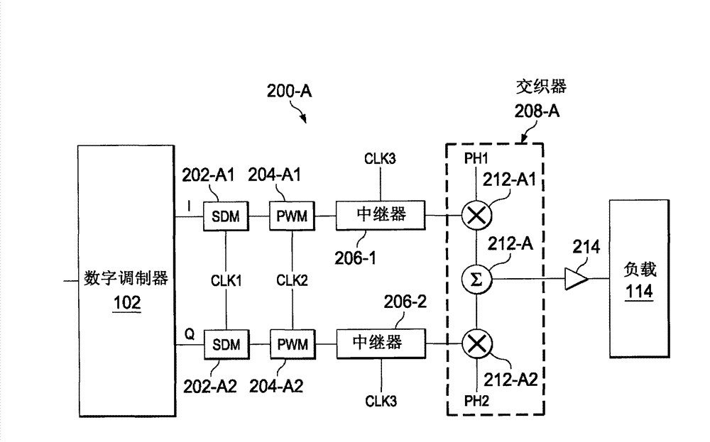
[0029] Turn to Figure 3-6 , Shows an example of the digital transmitter 200-A according to the present invention. As shown, the digital modulator 102 is capable of generating I and Q signals (similar to Figure 2 above). SDM 202-A1 and 202-A2 (they are typically low-pass multi-bit SDMs with M output levels) receive I and Q signals from the digital modulator 102, respectively. These SDM202-A1 and 202-A2 are usually determined by the clock signal CLK1 (which may for example have a frequency F S ) Provides a clock to filter the I and Q signals, thereby reducing the use of some out-of-band noise (such as Figure 4 Shown) the number of bits of the I and Q signals. The pulse width modulators or PWM204-A1 and 204-A2 (which can be low-pass PWMs, for example) receive the filtered I and ...


PUM


Abstract

The inveniton relates to a digital time-interleaved RF-PWM transmitter. The method for transmitting radio frequency (RF) signals is provided. In-phase (I) and quadrature (Q) signals are received and filtered using sigma-delta modulation. I and Q pulse width modulation signals are generated from the filtered I and Q signals and interleaved so as to generate a time-interleaved signal. The time-interleaved signal is then amplified to generate the RF signals.

Description

Technical field [0001] The present invention relates generally to radio frequency (RF) transmitters, and more particularly to RF pulse width modulation (PWM) transmitters. Background technique [0002] In many conventional applications such as wireless local area network (WLAN) or long-term evolution (LTE), the signal operates at low amplitude, which has a peak-to-average ratio and causes impairment of transmitter performance. This is partly due to the performance of conventional power amplifiers (PA) at these peak-to-average ratios, where the power efficiency decreases exponentially. This is shown in Figure 1, which compares the performance of a class AB amplifier, a switch PA, and a Doherty PA. As shown in the figure, Doterty PA has the best performance, but this type of PA is relatively large (using high-power combiners that are not suitable for CMOS technology), and is usually used in base stations. Switch PA (which can use polar or linear amplification with nonlinear compo...

Claims


Application Information

Patent Timeline
IPC IPC(8): H04B1/02H04L1/00
CPCH04B1/04H04L1/0071
Inventor R·何扎L·丁J·胡尔B·S·哈罗恩
Owner TEXAS INSTR INC
Why Eureka
Try Eureka