Spindle motor

A technology of spindle motor and motor rotor, applied in electrical components, electromechanical devices, electric components, etc., can solve problems such as separation, loosening, and weakening of hub connection force.

Inactive Publication Date: 2013-06-26
SAMSUNG ELECTRO MECHANICS CO LTD
View PDF5 Cites 0 Cited by
  • Summary
  • Abstract
  • Description
  • Claims
  • Application Information

AI Technical Summary

Problems solved by technology

The connection of components including the hub is loosened due to vibration, etc. generated when the spindle motor is driven, or some parts are detached from the spindle motor due to external impact, etc., so that the operation reliability of the spindle motor is deteriorated
In addition, the hub connected to the shaft cannot withstand the vibration generated when the spindle motor is driven due to the weakening of the connection force of the hub, so that the hub may be separated from the shaft upward in the axial direction
In addition, even in the case where a stopper is formed to support the assembly including the hub and the sleeve, the connecting force between the hub and the stopper is still small, so it is difficult to fix and support the hub and the sleeve , and, the adhesive filled when connecting the hub and the stopper flows along the shafting forming the hydrodynamic bearing part, causing foreign matter to mix with the working fluid

Method used


Image

  • Spindle motor
  • Spindle motor
  • Spindle motor

Examples


Embodiment Construction

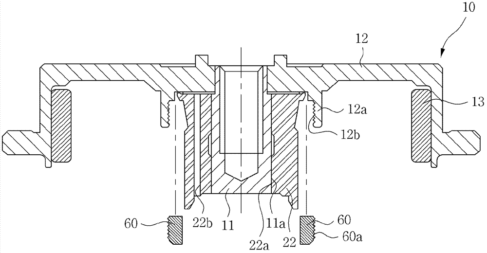
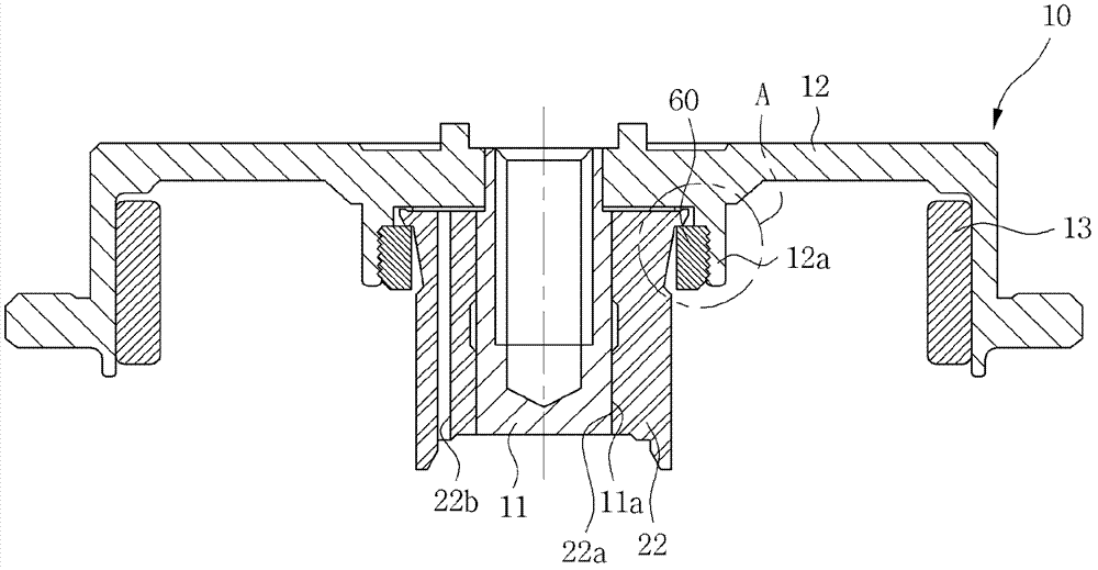
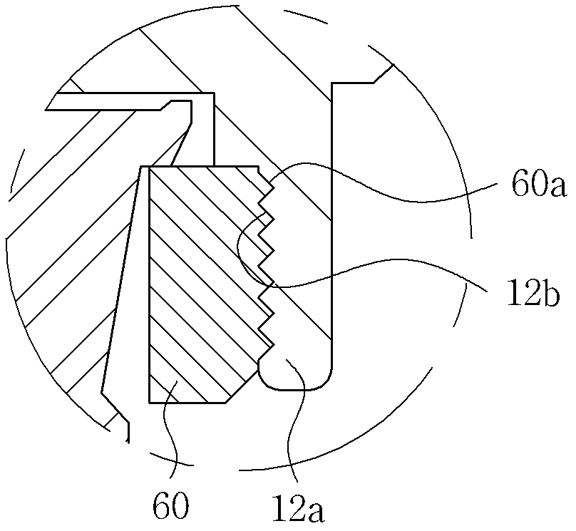
[0020] Many features and advantages of the present invention will be more apparent from the following description of the embodiments in conjunction with the accompanying drawings.

[0021] The terms and words used in this specification and claims should not be construed as being limited to their typical meanings or dictionary definitions, but should be construed as having meanings and concepts related to the technical scope of the present invention based on the following rules, according to which, The inventor can appropriately define the concepts of the terms to best describe the best method known to him or her for carrying out the invention.

[0022] The above and other objects, features and advantages of the present invention will be more clearly understood from the following detailed description in conjunction with the accompanying drawings. In the specification, when adding reference numerals to components of all drawings, it should be noted that the same reference numera...


PUM


Abstract

Disclosed herein is a coupling structure for coupling a stopper supporting a hub and a sleeve of a spindle motor to a protrusion part of the hub. Particularly, coupling force between the stopper and the protrusion part of the hub is improved, thereby making it possible to improve reliability in coupling between the hub and the sleeve. In addition, it is possible to maintain coupling reliability of an assembly of the hub and the sleeve against vibration generated at the time of driving of the motor, external impact, or the like.

Description

[0001] Cross References to Related Applications [0002] This application claims the priority of the Korean Patent Application No. 10-2011-0140921 entitled "Spindle Motor" filed on December 23, 2011, the entire content of which is hereby incorporated as The references are incorporated into this application. technical field [0003] The invention relates to a spindle motor. Background technique [0004] In general, a spindle motor belonging to a brushless DC motor (BLDC) is widely used as a laser beam scanning motor of a laser printer, a motor of a floppy disk drive (FDD), a motor for, for example, a compact disk (CD) or a digital versatile disk (DVD). ), etc., and the motor of a hard disk drive. [0005] Recently, in devices such as hard disk drives that require large-capacity and high-speed driving force, spindle motors including hydrodynamic pressure bearings are commonly used to minimize the generation of noise and non-repetitive radial runout (NRRO), which Repetitive ...

Claims


Application Information

Patent Timeline
Patent Type & Authority Applications(China)
IPC IPC(8): H02K5/16
CPCG11B19/2009H02K1/30H02K5/1675G11B19/20
Inventor 梁景琇
Owner SAMSUNG ELECTRO MECHANICS CO LTD
Why Eureka
Try Eureka