Method and device for producing yarn

A yarn and twisting device technology, which is applied to spinning machines, textiles and papermaking, and open-end spinning machines, etc., can solve problems such as the inability to achieve stable yarn solidification, yarn breakage, and gradual disappearance

Active Publication Date: 2017-04-19
SAURER GERMANY GMBH & CO KG
View PDF8 Cites 0 Cited by
  • Summary
  • Abstract
  • Description
  • Claims
  • Application Information

AI Technical Summary

Problems solved by technology

Since in this known device the false twist has been lost again in the area behind the yarn delivery feeder in the withdrawal direction, yarn stabilization may not be possible in this area, so yarn breakage may occur especially here
[0012] Therefore, if additional twisting is to be added to the yarn by means of false twisting, the disadvantage of this known device is that the false twisting already disappears gradually in the cylindrical pipe section of the yarn feeder or at least immediately thereafter.

Method used


Image

  • Method and device for producing yarn
  • Method and device for producing yarn
  • Method and device for producing yarn

Examples


Embodiment Construction

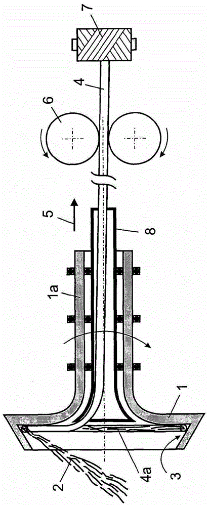
[0062] figure 1 A device according to known prior art is shown. The fiber 2 fed to the wall of the rotor 1 slides into the rotor groove 3 by centrifugal force and is "caught" by the yarn end 4a rotating with the rotor 1 . The yarn 4 is drawn off in direction 5 via the rotor shaft 1a. Yarn 4 is drawn off via draw-off roller 6 and wound onto bobbins 7 . For drawing, these rollers 6 are rotated towards each other, so that the yarn 4 arranged between the rollers is conveyed.

[0063] In this case, a yarn feeder 8 is provided rotatably inside the rotor shaft, through which the yarn 4 is drawn inside. At this moment, the yarn 4 rolls on the inner wall of the yarn feeder 8 and obtains false twist, but only in the area of ​​the rotor 1 .

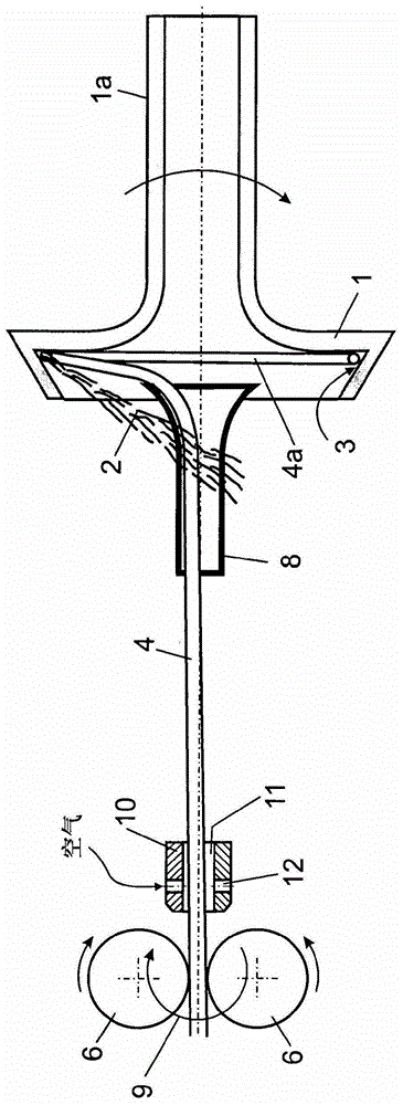
[0064] figure 2 shows an arrangement according to the invention, where the fibers 2 fed to the rotor 1 are merged into the yarn 4 in the rotor groove 3 and the yarn 4 passes through the feed nozzle 8 along the opposite direction to the rotor a...


PUM


Abstract

The invention relates to a method for producing a fibre yarn (4), in which fibres (2) to be spun are fed to a rotating spinning rotor (1), are doubled in same and are drawn off from the spinning rotor (1) as fibre yarn (4) by means of a draw-off device (6), wherein upon drawing-off from the spinning rotor (1) a false twist is imposed on the fibre yarn (4), as during drawing-off the draw-off device (6) rotates about the longitudinal axis of the fibre yarn, and in particular draw-off rollers (6) that turn in opposite directions rotate together about the longitudinal axis of the fibre yarn. The invention further relates to a draw-off device for drawing-off spun fibre yarn (4) from a spinning rotor (1) comprising two draw-off rollers (6) which can turn in opposite directions and between which the fibre yarn (4) can be clamped and which by turning can draw the fibre yarn (4) around the rollers (6a), the draw-off device including a rotor (20) having a hollow shaft (21) through which the fibre yarn (4) can be guided coaxially with respect to the hollow shaft axis (22), wherein the rotor (20) is driven or at least can be driven in rotation about the hollow shaft axis / longitudinal axis of the fibre yarn (22) and includes the draw-off rollers (6), the roller axes (6a) of which are oriented perpendicular to the hollow shaft axis (22).

Description

technical field [0001] The invention relates to a method and a device for producing yarn with low yarn twist for further processing in subsequent process steps such as textile machines, wherein the fibers to be spun are supplied to rotating spinning rotors in which is twisted in the cup and drawn as yarn from the spinning rotor, the yarn is given a false twist as it is withdrawn from the spinning rotor, especially an independently adjustable false twist, in particular except through the rotor and depending on The false twist effect of the process on the yarn feeder imparts twist. [0002] In particular, the invention relates to a drawing device for drawing spun yarn from a spinning rotor, comprising two drawing rollers rotatable in opposite directions, between which the yarn can be clamped and through which the yarn can be passed The roll is extracted by rotation about the roll axis. Background technique [0003] Such methods and devices are known in the prior art, for exa...

Claims


Application Information

Patent Timeline
Patent Type & Authority Patents(China)
IPC IPC(8): D01H4/08D01H4/40D01H7/92
CPCD01H4/08D01H4/40D01H7/923D02G1/022
Inventor K-H·G·莱曼T·G·葛瑞斯I·瑞恩巴赫M·莱娜B·阿斯兰D·皮尔奇S·佐贝尔F·维德纳
Owner SAURER GERMANY GMBH & CO KG
Why Eureka
Try Eureka