
Power transmission device

一种动力传送、电力的技术,应用在动力传送装置领域,能够解决执行器操作感觉恶化、动作速度降低等问题,达到抑制无用的消耗、防止转速的降低、防止操作感觉的恶化的效果

Inactive Publication Date: 2013-06-26
YANMAR POWER TECHNOLOGY CO LTD
View PDF6 Cites 1 Cited by
  • Summary
  • Abstract
  • Description
  • Claims
  • Application Information

AI Technical Summary

Problems solved by technology

Accordingly, it is disadvantageous that the operating speed of the actuator decreases, and the operator's feeling of operating the actuator deteriorates.

Method used


Image

  • Power transmission device
  • Power transmission device
  • Power transmission device

Examples


Embodiment Construction

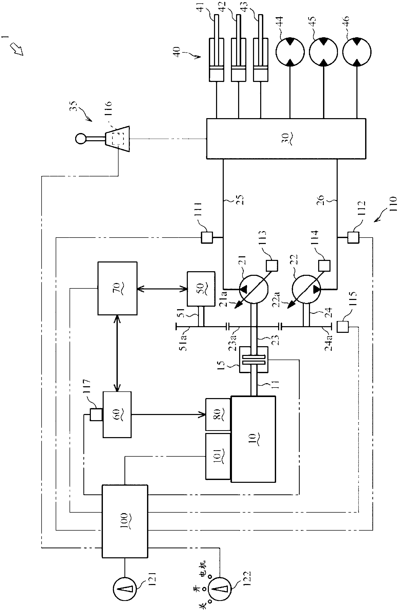
[0031] Next, use figure 1 , the power transmission device 1 according to one embodiment of the present invention will be described.

[0032] The power transmission device 1 transmits power from a drive source to drive various actuators.

[0033] The power transmission device 1 includes an engine 10 , a first hydraulic pump 21 , a second hydraulic pump 22 , a clutch 15 , a control valve 30 , a working hydraulic actuator 40 , an operating member 35 , a motor generator 50 , a battery 60 , and an inverter 70 . , battery motor 80, absorbed horsepower detection member 110, operation state detection member 116, charge state detection member 117, engine speed setting member 121, idle stop selection member 122, engine controller unit 101 and main controller 100.

[0034] In addition, although the power transmission device 1 of this embodiment is made into the power transmission device with which a hydraulic shovel is equipped, this invention is not limited to this. That is, it may be...


PUM


Abstract

Provided is a power transmission device with which it is possible to alleviate wasteful fuel consumption and prevent deterioration in the operating sensitivity of an actuator when restarting an engine. The power transmission device is provided with control devices (main controller (100) and ECU (101)) which, upon detecting that a console means (35) has not been operated for a prescribed time (non-operation adjudication threshold t1) or longer, shut off an engine (10), interrupt a clutch (15), and block the supply of power from a battery (60) to a motor generator (50); upon detecting thereafter that the console means (35) has been operated, activate the engine (10) with a cell motor (80) and allow the supply of power from the battery (60) to the motor generator (50); and after the RPMs (Ne) of the engine (10) reach or exceed a prescribed value (RPM Np), carry out an idling stop control, connecting the clutch (15) and blocking the supply of power from the battery (60) to the motor generator (50).

Description

technical field [0001] The present invention relates to technology of a power transmission device using an engine and an electric motor. Background technique [0002] Conventionally, technologies related to a power transmission device that automatically stops or starts an engine under predetermined conditions have been known. For example, as described in Patent Document 1. [0003] The power transmission device described in Patent Document 1 includes an engine as a power source, a hydraulic pump for discharging hydraulic fluid, a clutch interposed between an output shaft of the engine and an input shaft of the hydraulic pump, and an input shaft of the hydraulic pump. A connected electric motor (electric motor), a flywheel fixed to an input shaft of the electric motor, an actuator driven by hydraulic oil supplied from a hydraulic pump, and an operating member for operating the actuator. [0004] With near no load applied to the actuator, the clutch is disengaged, the engine...

Claims


Application Information

Patent Timeline
Patent Type & Authority Applications(China)
IPC IPC(8): E02F9/20F02D29/00F02D29/02F02D29/04F02D29/06
CPCE02F9/2075E02F9/2079F02D29/02F02D29/04E02F9/2246E02F9/2292E02F9/2296Y10S903/93B60W20/20B60W20/11B60W10/08B60W2300/17B60W10/06Y02T10/62B60W2556/00B60W10/02B60W10/26B60W20/40
Inventor 绪方永博宫川健司
Owner YANMAR POWER TECHNOLOGY CO LTD
Learn More