Component subpackaging fixer

A technology of parts and fixtures, which is applied in the field of tooling and fixtures, can solve the problems of high labor intensity, high cost, and many devices, and achieve the effects of reducing labor intensity, facilitating support, and high versatility

Inactive Publication Date: 2013-07-03
LANZHOU GEELY AUTOMOBILE IND +1
View PDF7 Cites 11 Cited by
  • Summary
  • Abstract
  • Description
  • Claims
  • Application Information

AI Technical Summary

Problems solved by technology

[0004] The present invention mainly aims at the problems that existing auto parts sub-packaging and fixing devices have many devices, high cost, poor versatility, large space occupied by sub-pack...

Method used


Image

  • Component subpackaging fixer
  • Component subpackaging fixer
  • Component subpackaging fixer

Examples


Embodiment 1

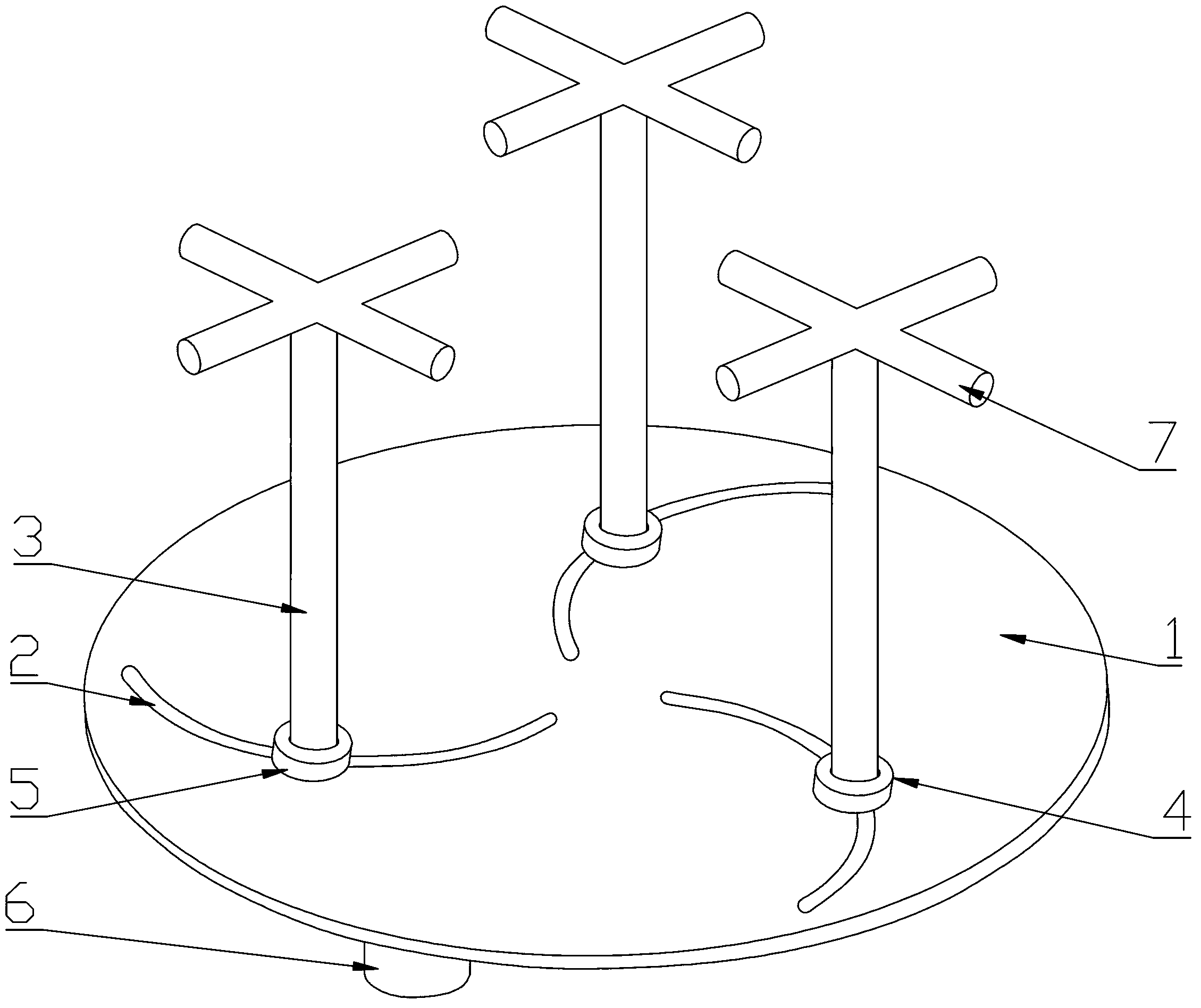
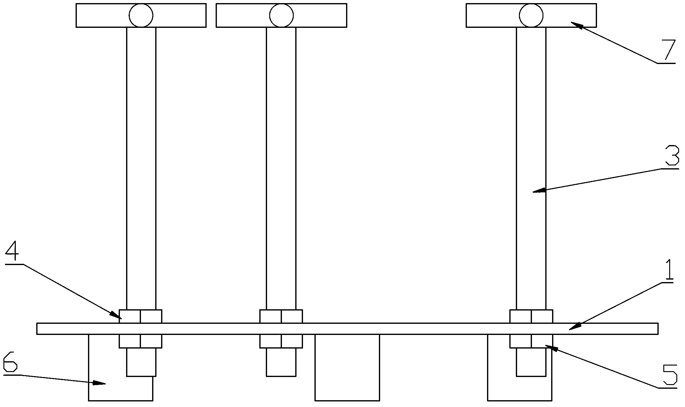
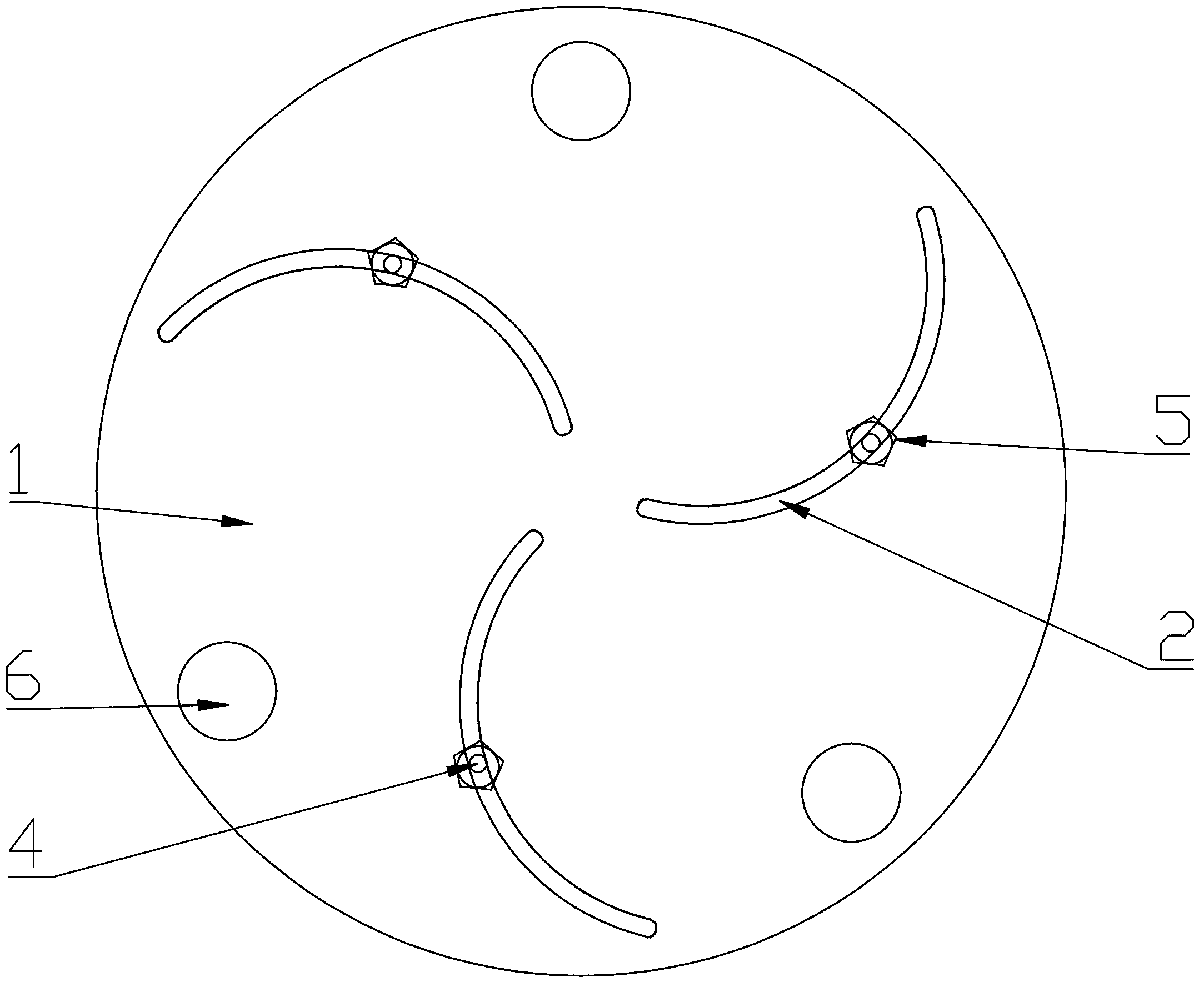
[0025] As attached to the manual figure 1 , 2 , shown in 3, a kind of parts subpackage fixer, comprises subpackage platform 1 and three struts 3, and brace bar 3 is a straight bar and is vertical with subpackage platform 1, and subpackage platform 1 is a circular plate, subpackage The platform 1 is provided with three arc-shaped grooves 2 that pass through the sub-packaging platform 1. The arc-shaped grooves 2 are "C"-shaped grooves. The three arc-shaped grooves 2 are distributed in a clockwise spiral along the center of the sub-packaging platform 1. The arrangement of the plurality of arc-shaped grooves 2 in the scheme is the same as that of the impeller blades. The positions of the struts 3 correspond to the positions of the arc-shaped grooves 2. The groove width of the arc-shaped grooves 2 is larger than the diameter of the struts 3. The struts One end of 3 extends into the corresponding arc-shaped groove 2 and cooperates with the sub-packing table 1 in clearance. Each str...

Embodiment 2

[0028] As attached to the manual Figure 4 As shown, the scheme includes two arc-shaped grooves 2 and two struts 3, the arc-shaped grooves 2 are "C"-shaped grooves, the two arc-shaped grooves 2 are distributed in an "X" shape, and the two struts 3 are connected. , others remain unchanged as in Example 1.

[0029] As attached to the manual Figure 5 As shown, the arc-shaped groove 2 in the above scheme can also be an "S"-shaped groove, the two arc-shaped grooves 2 are distributed in an "X" shape, and the two struts 3 are connected, and the others remain unchanged as in Embodiment 1.

Embodiment 3

[0031] As attached to the manual Image 6 As shown, the scheme includes two arc-shaped grooves 2 and two struts 3, the arc-shaped grooves 2 are "C"-shaped grooves, and the two arc-shaped grooves 2 are symmetrically distributed along the center line of the sub-packing table 1, and others such as Embodiment 1 remains unchanged.


PUM


Abstract

The invention relates to a component subpackaging fixer. The component subpackaging fixer comprises a subpackaging table, wherein a plurality of arc-shaped grooves are formed in the subpackaging table; the arc-shaped grooves are distributed in the subpackaging table according to certain geometrical shapes; a plurality of supporting rods are arranged on the subpackaging table; the number of the supporting rods is equal to the number of the arc-shaped grooves; and the positions of the supporting rods correspond to the positions of the arc-shaped grooves one by one; the supporting rods are connected with the insides of the corresponding arc-shaped grooves and are in clearance fit with the subpackaging table; positioning structures are connected onto the supporting rods; and the supporting rods are fixedly connected with the subpackaging table in a detachable way through the positioning structures. The component subpackaging fixer has the advantages as follows: 1, one component subpackaging fixer is applicable to multiple automobile components with different structures and shapes, so that the number of component subpackaging devices is reduced, the generality is high, and the labor intensity is reduced; 2, the arc-shaped grooves provide more moving positions for the supporting rods, so that the components with different structures and shapes can be supported easily and the generality is high; and the edges of the arc-shaped grooves are smooth, so that supporting rods can slide smoothly; and 3, the supporting rods can move up and down relative to the subpackaging table, so that different components can be supported easily.

Description

technical field [0001] The invention relates to a tooling fixture, in particular to a component subassembly fixture with high versatility used for subassembly of parts during automobile production. Background technique [0002] In the production of complete automobiles, especially in the final assembly process, a large number of parts need to be sub-assembled, and the sub-assembled parts form a parts assembly, which is then assembled to the complete car. Especially for many smaller stamping parts or parts with mechanical functions, due to their small size, complex mechanical structure and shape, when subpackaging such auto parts, they must first be fixed before they can be effectively subpackaged. Just need a fixer to fix it. At present, the fixing devices used in the subassembly of parts in automobile production usually correspond to at least one special fixing device for parts subassembly. If the auto parts to be repacked require multiple processes Subpackage, then it is...

Claims


Application Information

Patent Timeline
IPC IPC(8): B25B11/02
Inventor 魏斌刘关高祎博晁海林
Owner LANZHOU GEELY AUTOMOBILE IND
Why Eureka
Try Eureka