
Dynamic static pressure mixing main shaft device

A main shaft device, dynamic and static pressure technology, applied in the directions of bearings, shafts and bearings, mechanical equipment, etc., can solve the problems of contact wear between the main shaft and the bearing, lack of dynamic pressure effect, etc., to avoid contact wear and improve the effect of dynamic pressure effect.

Inactive Publication Date: 2013-07-03
周小明
View PDF0 Cites 5 Cited by
  • Summary
  • Abstract
  • Description
  • Claims
  • Application Information

AI Technical Summary

Problems solved by technology

General bearings are only suitable for occasions with constant external loads, not suitable for mechanical spindle systems with alternating loads, and when starting, the spindle and bearings are prone to contact wear, and the dynamic pressure effect is still slightly lacking during operation.

Method used


Image

  • Dynamic static pressure mixing main shaft device
  • Dynamic static pressure mixing main shaft device

Examples


Embodiment Construction

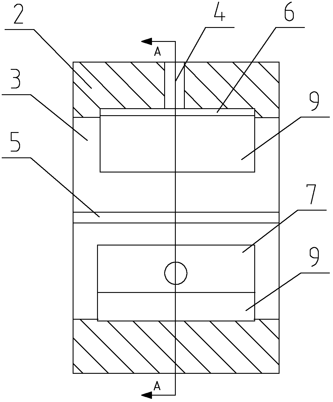
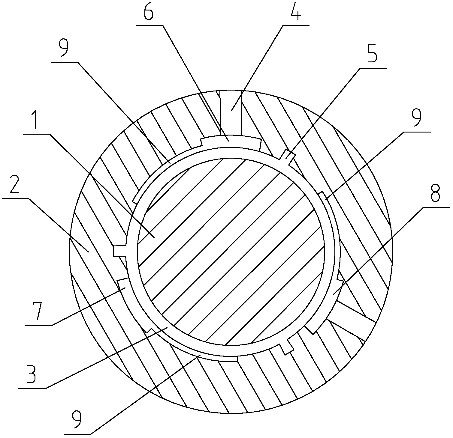
[0011] The present invention will now be further described in conjunction with the accompanying drawings and preferred embodiments. These drawings are all simplified schematic diagrams, which only illustrate the basic structure of the present invention in a schematic manner, so they only show the configurations related to the present invention.

[0012] Such as figure 1 with figure 2 A dynamic and static pressure hybrid spindle device shown includes a spindle 1 and a bearing 2 corresponding to the spindle 1. There is a dynamic pressure chamber 3 between the spindle 1 and the bearing 2, and an oil inlet hole 4 and an axial oil return groove are opened on the bearing 2. 5. The bearing 2 is provided with a static pressure oil chamber on the surface opposite to the main shaft 1, and the static pressure oil chamber includes an upper static pressure oil chamber 6, a lower static pressure oil chamber 7 and a front static pressure oil chamber 8 at 120° to each other.

[0013] In or...


PUM


Abstract

The invention discloses a dynamic static pressure mixing main shaft device which comprises a main shaft and a bearing disposed correspondingly with the main shaft; a dynamic pressure chamber is disposed between the main shaft and the bearing; an oil inlet and an axial oil return groove are disposed on the bearing; a static pressure oil chamber is disposed on a surface of the bearing opposite to the main shaft; the static pressure oil chamber comprises an upper static pressure oil chamber, a lower static pressure oil chamber, and a front static pressure oil chamber with a 120-degree included angle between each other. The dynamic static pressure mixing main shaft device provided by the invention prevents contact abrasion between the main shaft and the bearing, improves dynamic pressure effect, and is suitable for situations of alternating loads.

Description

technical field [0001] The invention relates to a dynamic and static pressure mixing spindle device. Background technique [0002] Currently, hydrostatic bearings are designed using a mixture of hydrostatic and hydrodynamic effects. When starting and working, relying on the static pressure oil chamber and the dynamic pressure chamber formed by the main shaft and the bearing to carry the external load, the oil film has high rigidity. General bearings are only suitable for occasions with constant external loads, not for mechanical spindle systems with alternating loads, and when starting, the spindle and bearings are prone to contact wear, and the dynamic pressure effect is still slightly lacking during operation. Contents of the invention [0003] The technical problem to be solved by the present invention is: to overcome the deficiencies in the prior art, to provide a dynamic and static pressure hybrid spindle device which can avoid the contact wear between the spindle an...

Claims


Application Information

Patent Timeline
Patent Type & Authority Applications(China)
IPC IPC(8): F16C32/00F16C32/06
Inventor 周小明
Owner 周小明
Learn More