Vibration-type driving device

a driving device and vibration-type technology, applied in piezoelectric/electrostrictive/magnetostrictive devices, piezoelectric/electrostriction/magnetostriction machines, electrical equipment, etc., can solve the problems of reducing the reducing the amount of wear at the contact region of the driven object, and reducing the operating life of the vibration-type driving device. , to prevent the effect of increasing the amount of wear at the conta

Inactive Publication Date: 2014-04-22
CANON KK
View PDF11 Cites 2 Cited by
  • Summary
  • Abstract
  • Description
  • Claims
  • Application Information

AI Technical Summary

Benefits of technology

[0008]The present invention prevents an increase in the amount of wear of the contact region of a driven object to prevent a decrease in the operating life of a vibration-type driving device that uses a plurality of vibrators.
[0010]The present invention can prevent the wear of the contact region of a driven object from being worsened to prevent a decrease in the operating life of a vibration-type driving device that uses a plurality of vibrators.

Problems solved by technology

One problem with the vibration-type driving device using a vibrator of the type in which vibrations in different vibration modes are combined has a plurality of vibrators to ensure the output is a decrease in operating life.
Therefore, the amount of wear at the contact regions of the driven object increases substantially in proportion to an increase in the number of vibrators, as compared with a case in which one vibrator is used.
This may promote the decrease of the life of the vibration-type driving device.
Furthermore, for the case where only the amount of wear of a portion of the contact regions is larger than that at the other portions, the life may expire because the amount of wear of the portion reaches the limit even if the other portions maintain the performance.

Method used


Image

  • Vibration-type driving device
  • Vibration-type driving device
  • Vibration-type driving device

Examples


first embodiment

[0029]In this embodiment, a vibration-type driving device applied to a device that requires not a continuous rotation driving operation but a reciprocating operation at a desired rotation angle will be described. For example, it is used in a lens linear motion mechanism using the rotary motion of a cylindrical rotary cam or in aperture driving using a rotary motion in a lens drive mechanism.

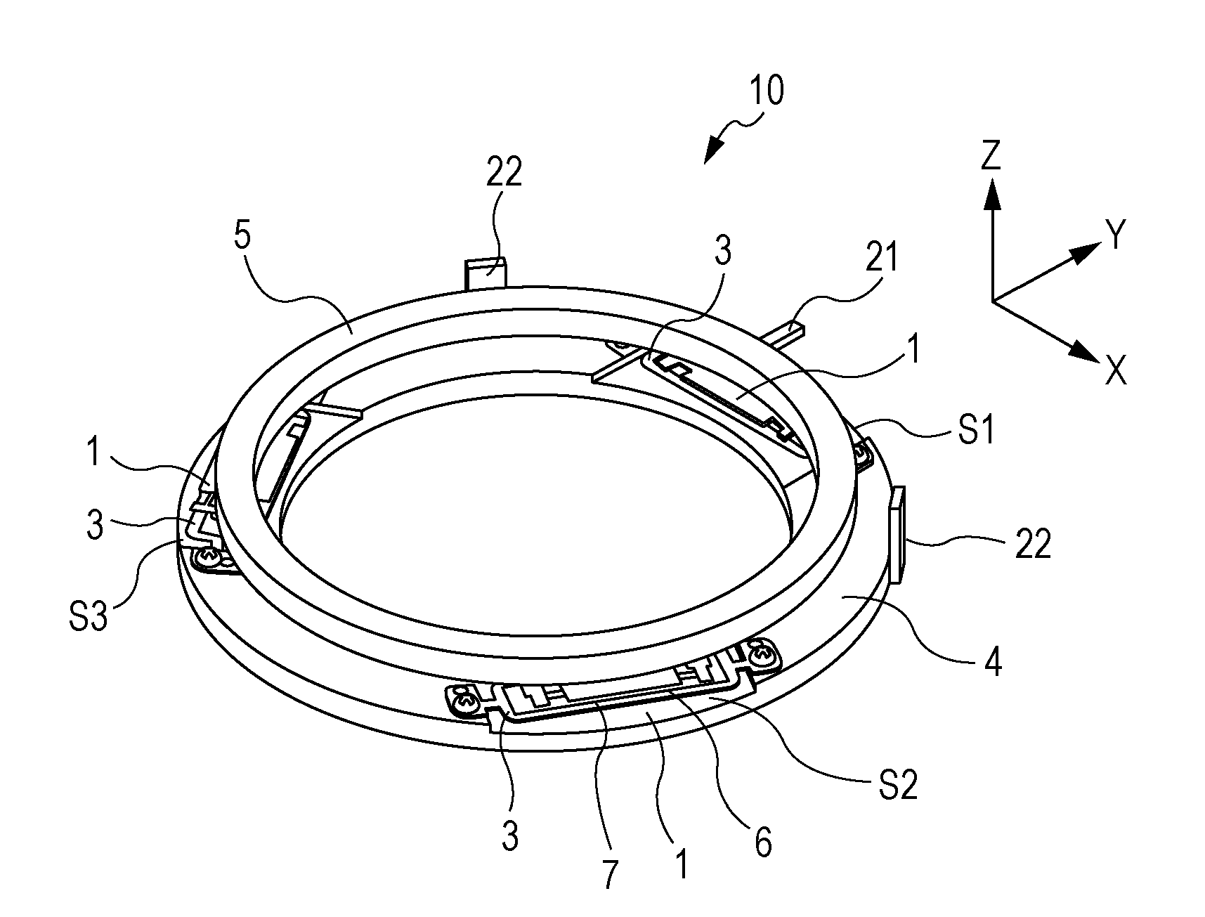
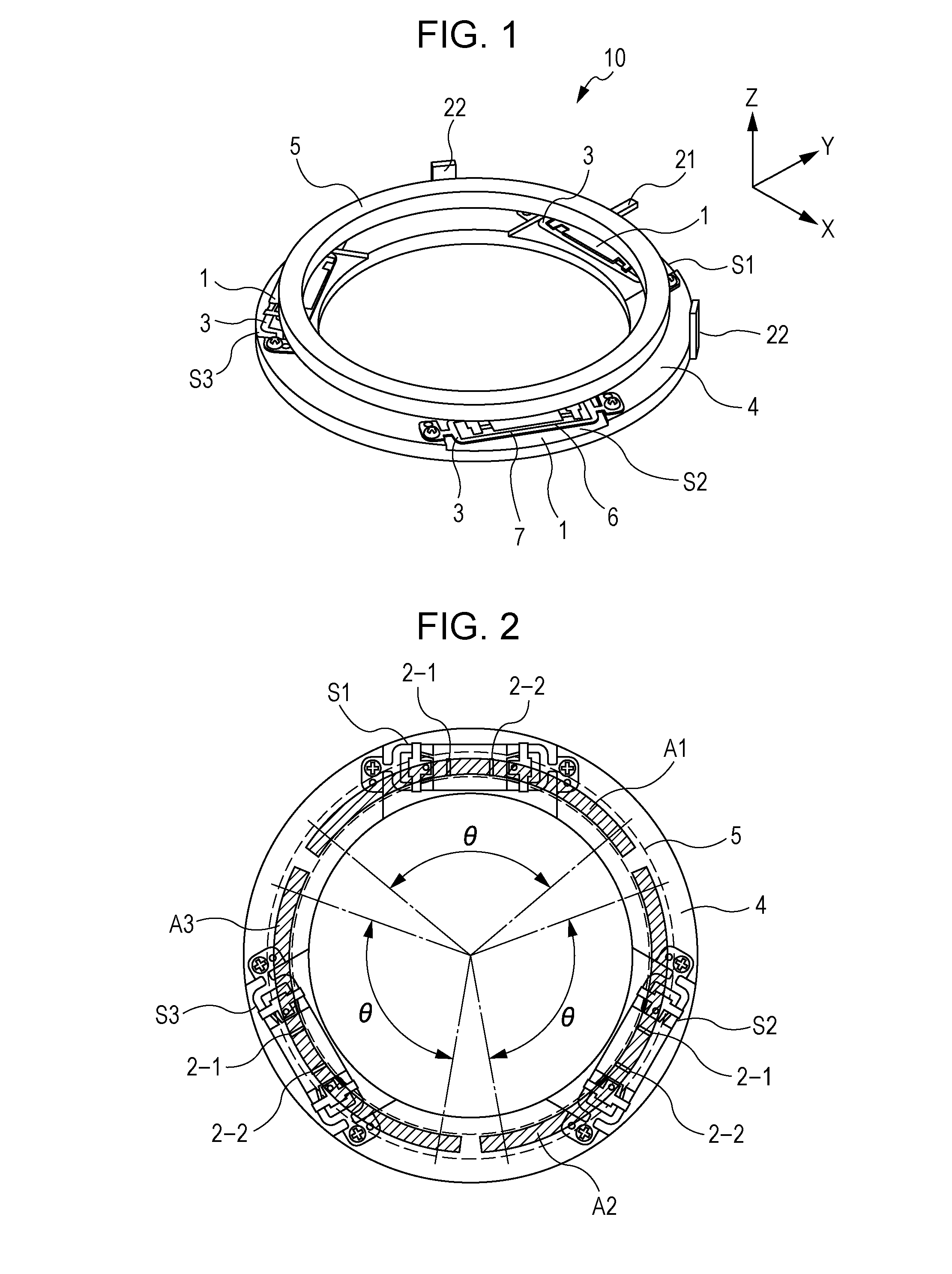
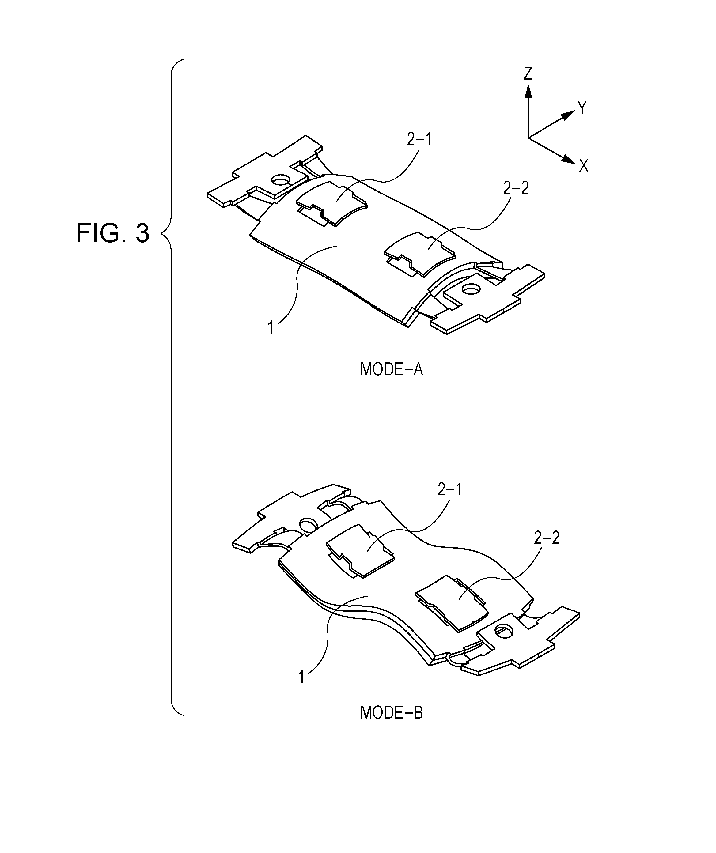
[0030]FIG. 1 is a perspective view showing the configuration of the principal part of a vibration-type driving device 10 according to a first embodiment of the present invention. The vibration-type driving device 10 in FIG. 1 includes three vibrator units S1, S2, and S3, a holding member 4 that holds the vibrator units S1, S2, and S3, and the driven object 5 held in pressure contact with the vibrator units S1, S2, and S3. The vibrator units S1, S2, and S3 have the same shape, each of which is composed of a vibrator 1 and a joint member 3 that joins the vibrator 1 to the holding member 4. The vibr...

second embodiment

[0039]In this embodiment, a vibration-type driving device applied to continuous rotation driving will be described. FIG. 5 is a perspective view showing the configuration of the principal part of a vibration-type driving device 10 of a second embodiment of the present invention. Descriptions of the same components as those of the vibration-type driving device 10 of the first embodiment shown in FIG. 1 are omitted, and only differences will be described. FIG. 6 is a plan view of the vibration-type driving device 10 shown in FIG. 5, in which the driven object 5 is shown, only in outline, by a chain line so that the positions and shapes of the vibrator units S1, S2, and S3 can be understood. The contact regions of the driven object 5 are denoted by A1, A2, and A3 in correspondence with the vibrator units S1, S2, and S3, respectively. The vibrator units S1, S2, and S3 are located at positions on the holding member 4, at which the circumference is divided into substantially three equal p...

third embodiment

[0041]In a vibration-type driving device of this embodiment, the vibrators are disposed on the side of the driven object 5, unlike the first and second embodiments. FIG. 7 is a perspective view that schematically shows the configuration of a vibration-type driving device 10 of a third embodiment of the present invention. In this embodiment, the driven object 5 is substantially cylindrical in shape, and the contact regions of the driven object 5 are formed on the outer peripheral side. The driven object 5 is held so as to be rotatable about the central axis of the cylinder relative to the holding member 4, and other axial rotations and translational movement are restricted.

[0042]The vibrator units S1, S2, and S3 are fixed by the holding member 4 in such a manner that the upper surfaces of the projections, which are to come into contact with the driven object 5, are in contact with the outer peripheral surface of the driven object 5. The configuration of the vibrators is the same as t...


PUM


Abstract

A vibration-type driving device according to the present invention includes a plurality of vibrators in which contact portions perform an elliptical motion using a combination of vibrations in different vibration modes; and a driven object having contact regions that come into contact with the contact portions and move relative to the plurality of vibrators, wherein the contact regions for the individual vibrators differ in position so as not to overlap.

Description

BACKGROUND OF THE INVENTION[0001]1. Field of the Invention[0002]The present invention relates to vibration-type driving devices. Specifically, it relates to a vibration-type driving device that moves a vibrator and a driven object relative to each other using a combination of vibrations in different vibration modes.[0003]2. Description of the Related Art[0004]For a vibration-type driving device using a vibrator of the type in which vibrations in different vibration modes (shapes) are combined, a configuration in which a plurality of vibrators are provided to ensure the output has been proposed. U.S. Pat. No. 7,466,062 discloses a configuration in which a plurality of vibrators that generate a combination of vibrations in a longitudinal vibration mode in the longitudinal direction of the vibrator and an out-of-plane bending vibration mode are disposed on concentric circles and in which a driven object that is to come into pressure contact with the plurality of vibrators is rotated re...

Claims


Application Information

Patent Timeline
Patent Type & Authority Patents(United States)
IPC IPC(8): H02N2/10H02N2/02H02N2/12
CPCH02N2/004H02N2/103H02N2/026H02N2/001
Inventor KOJIMA, NOBUYUKI
Owner CANON KK
Why Eureka
Try Eureka