Current monitoring device

A current monitoring and current technology, which is applied in the direction of measuring device, voltage/current isolation, measuring current/voltage, etc., can solve the problems of Hall sensor damage, large range of measuring current accuracy, and the failure of current transformers to realize functions, etc.

Active Publication Date: 2013-07-03
SCHNEIDER ELECTRIC IND SAS
View PDF4 Cites 12 Cited by
  • Summary
  • Abstract
  • Description
  • Claims
  • Application Information

AI Technical Summary

Problems solved by technology

However, since the DC three-stage protection in low-voltage power distribution needs to protect a wide range of currents to achieve overload protection, short-circuit short-delay protection, and short-circuit instantaneous protection, the range of measurement current accuracy must be large.
For example, for a

Method used


Image

  • Current monitoring device
  • Current monitoring device
  • Current monitoring device

Examples


Embodiment Construction

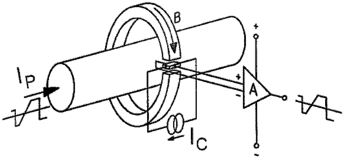
[0022] First, refer to figure 1 Describe the structure of a conventional current transformer.

[0023] Such as figure 1 As shown, only one copper bar and one Hall sensor are arranged in the traditional current transformer, and the copper bar is directly arranged through the central part of the Hall sensor. The defect of the traditional current transformer is that the range that the Hall sensor can monitor is not particularly large, so the problem that the Hall sensor is damaged or the entire current transformer cannot realize the function often occurs when the current is unstable.

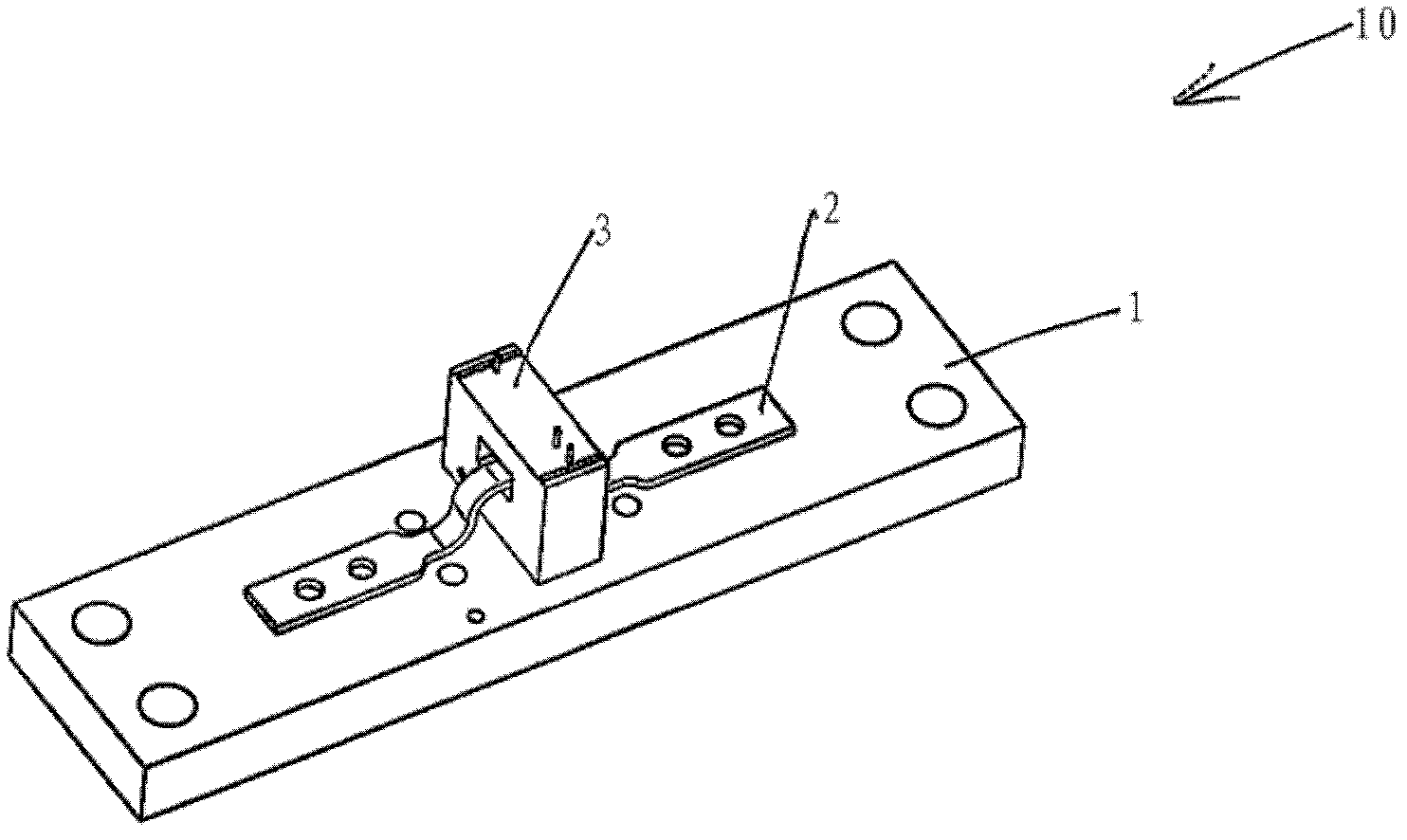
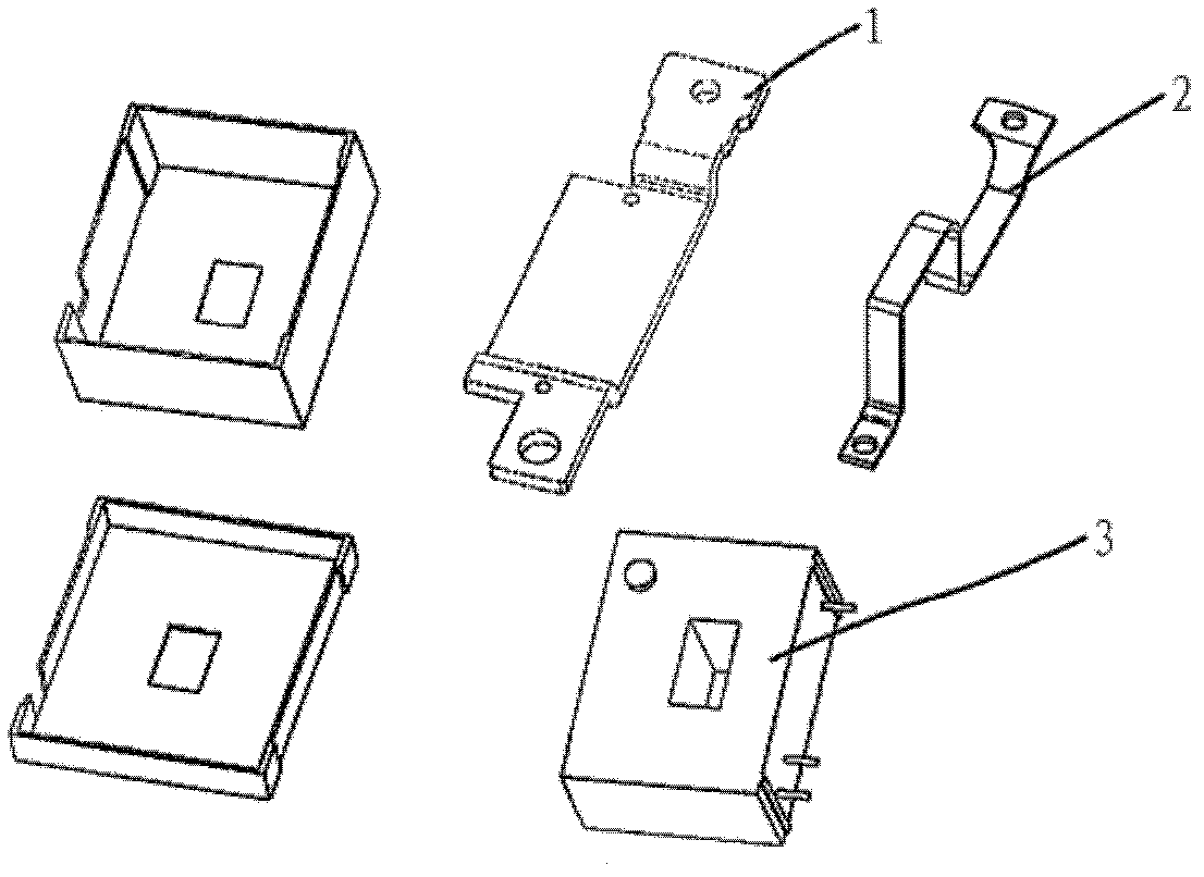
[0024] A first embodiment of the current monitoring device according to the present invention will be described below with reference to the drawings. The current monitoring device of this embodiment can be applied to the three-stage protection of direct current, and can also be applied to different direct current monitoring occasions, such as occasions of metering and displaying current.

[0025...


PUM


Abstract

The invention discloses a current monitoring device which comprises a first current bar main current bearing copper bar and a Hall sensor arranged on the first current bar main current bearing copper bar. The current monitoring device further comprises a second current bar arranged on the outer surface of the first current bar. The Hall sensor detects current which passes through the second current bar. The current monitoring device can measure the current accurately, at the same time lower cost and keep high stability.

Description

technical field [0001] The invention relates to current monitoring devices. Background technique [0002] In the current low-voltage electrical appliances, three-stage protection (LSI), namely, overload long-time delay protection, short-circuit short-time delay protection and short-circuit transient protection, can be used to realize safe operation of the power distribution system. However, the traditional way to realize LSI protection usually uses a bimetallic strip and a solenoid. The accuracy of the monitoring current is poor, and the current level cannot be adjusted, and the cooperation between the upper and lower levels is not very accurate. Moreover, in the terminal power distribution system, the problem of leapfrog tripping usually occurs, so that the continuity of power supply cannot be guaranteed. [0003] A conventional current transformer is generally constructed so that a copper bar passes through a Hall sensor to monitor the current flow. However, since the D...

Claims


Application Information

Patent Timeline
IPC IPC(8): G01R19/00G01R15/20
Inventor 吴蔚朱源
Owner SCHNEIDER ELECTRIC IND SAS
Why Eureka
Try Eureka