Pneumatic floor brush and vacuum cleaner thereof

A technology of pneumatic ground brushes and suction nozzles, which is applied to vacuum cleaners, suction nozzles, cleaning equipment, etc., can solve the problems such as the turbine can not be enlarged, the load capacity is poor, and achieve the effect of improving cleaning efficiency

Active Publication Date: 2013-07-10
ECOVACS ROBOTICS (SUZHOU ) CO LTD
View PDF6 Cites 7 Cited by
  • Summary
  • Abstract
  • Description
  • Claims
  • Application Information

AI Technical Summary

Problems solved by technology

However, since the turbine and the rolling brush are coaxially arranged, the turbine cannot be made larger, so there is a defect of poor load capacity

Method used


Image

  • Pneumatic floor brush and vacuum cleaner thereof
  • Pneumatic floor brush and vacuum cleaner thereof
  • Pneumatic floor brush and vacuum cleaner thereof

Examples


Embodiment Construction

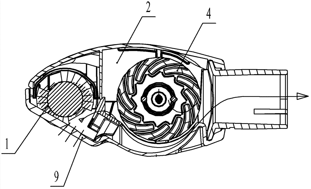
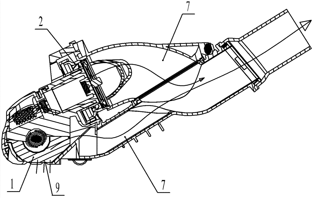
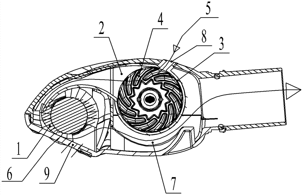
[0020] Such as image 3 As shown, in the working state of the pneumatic ground brush of the present invention, the dust-laden airflow 6 enters the brush chamber 1 from the dust suction port 9 and then enters the air duct 7; a drainage passage is set between the brush chamber and the turbine chamber, and the clean airflow 5 is Enter the turbine chamber 2 from the suction port 8, the clean air flow 5 flowing through the turbine chamber 2 enters the brush chamber 1 through the drainage channel, and finally enters the air duct 7, so that when the clean air flow 5 passing through the turbine chamber 2 enters the brush chamber 1 The dust in the dust-laden airflow 6 can be taken away, so that the clean airflow 5 passing through the turbine chamber 2 can be fully utilized. The turbine can be a radial fan, an axial fan or a mixed flow fan. The rotation of the turbine does not need to be driven by the dust-laden airflow 6, but is mainly driven by the clean airflow 5 before entering the ...


PUM


Abstract

The invention belongs to the technical field of household appliance manufacture and particularly relates to a pneumatic floor brush and a vacuum cleaner thereof. The pneumatic floor brush comprises a housing, a roll brush and a worm wheel, wherein the housing is provided with a roll brush chamber for accommodating the roll brush and a worm wheel chamber for accommodating the worm wheel; the worm wheel is used for driving the roll brush to rotate; dust airstream enters the roll brush chamber through a dust suction hole formed in the housing; clean airstream enters the worm wheel chamber through an air suction hole formed in the housing; a flow guide channel is formed between the roll brush chamber and the worm wheel chamber; the clean airstream flowing through the worm wheel chamber enters the roll brush chamber through the flow guide channel; and the roll brush is not coaxial with the worm wheel. According to the pneumatic floor brush, the problem of high possibility of worm wheel locking or low load capacity is solved, the clean airstream passing through the worm wheel is fully utilized, and the cleaning efficiency is improved.

Description

technical field [0001] The invention belongs to the technical field of manufacturing small household appliances for daily use, and in particular relates to a pneumatic ground brush and a vacuum cleaner thereof. Background technique [0002] The current vacuum cleaner generally includes a dust bucket, a filter assembly and a motor assembly, the dust bucket, the filter assembly and the motor assembly are located in a housing, and the motor assembly is connected to the dust bucket through the filter assembly. The motor components include the motor and the fan. When the motor is powered on, it drives the fan blades to run at high speed, forming an instant vacuum inside the vacuum cleaner. The air pressure inside the vacuum cleaner is much lower than the outside air pressure. The air flow enters the dust bucket of the vacuum cleaner along the suction nozzle and the air duct, and then is filtered by the filter assembly. The dust remains in the dust collection bag of the filter ass...

Claims


Application Information

Patent Timeline
Patent Type & Authority Applications(China)
IPC IPC(8): A47L9/04A47L5/22
CPCA47L9/0416A47L9/0477
Inventor 唐泽恒
Owner ECOVACS ROBOTICS (SUZHOU ) CO LTD
Why Eureka
Try Eureka