
Electrocardiogram measuring electrode holder and electrocardiograph

A technology of electrical measurement and electrodes, applied in diagnostic recording/measurement, medical science, sensors, etc., which can solve problems such as electrode position deviation, hygiene problems, and unsuitable for repeated use

Active Publication Date: 2013-07-10
心韵恒安医疗科技(北京)有限公司
View PDF8 Cites 2 Cited by
  • Summary
  • Abstract
  • Description
  • Claims
  • Application Information

AI Technical Summary

Problems solved by technology

[0011] However, the fastening and unfastening of the belt-shaped device disclosed in Patent Document 1 is time-consuming.
For the belt-shaped device disclosed in Patent Document 2, the adhesive layer may give an unpleasant feeling to the test subject
In addition, tape-shaped devices using adhesives are generally not suitable for repeated use, and the contact of adhesives with different subjects may cause hygienic problems, and repeated use will create fear of unhygienic
In addition, for an operator such as a doctor, the belt-shaped device disclosed in Patent Document 2 adheres to the chest of the test subject. If the belt-shaped device is placed in an improper position for the first time, it will be relatively troublesome to change the position of the belt-shaped device.
[0012] In addition, although the belt-shaped devices disclosed in Patent Document 1 and Patent Document 2 all have rectangular slits or strip-shaped holes that can finely adjust the position of the electrodes, they are suitable for use by testees with different chest sizes, but it will also cause problems , because the chest is not completely flat, so the electrode position may easily deviate from the original set position during use
[0013] When performing ECG measurements in hospitals or physical examination centers, there are often a large number of patients waiting for treatment or examination. A small inconvenience may make it difficult for the band-shaped device to be widely used in hospitals or medical examination centers where a large number of ECG measurements are required.
Therefore, there is a need for a belt-shaped device with a better feeling for the tested person and a simpler fixing device for the operator. In addition, the problem that the electrodes are prone to position deviation during the test should also be avoided.

Method used


Image

  • Electrocardiogram measuring electrode holder and electrocardiograph
  • Electrocardiogram measuring electrode holder and electrocardiograph
  • Electrocardiogram measuring electrode holder and electrocardiograph

Examples


no. 1 Embodiment

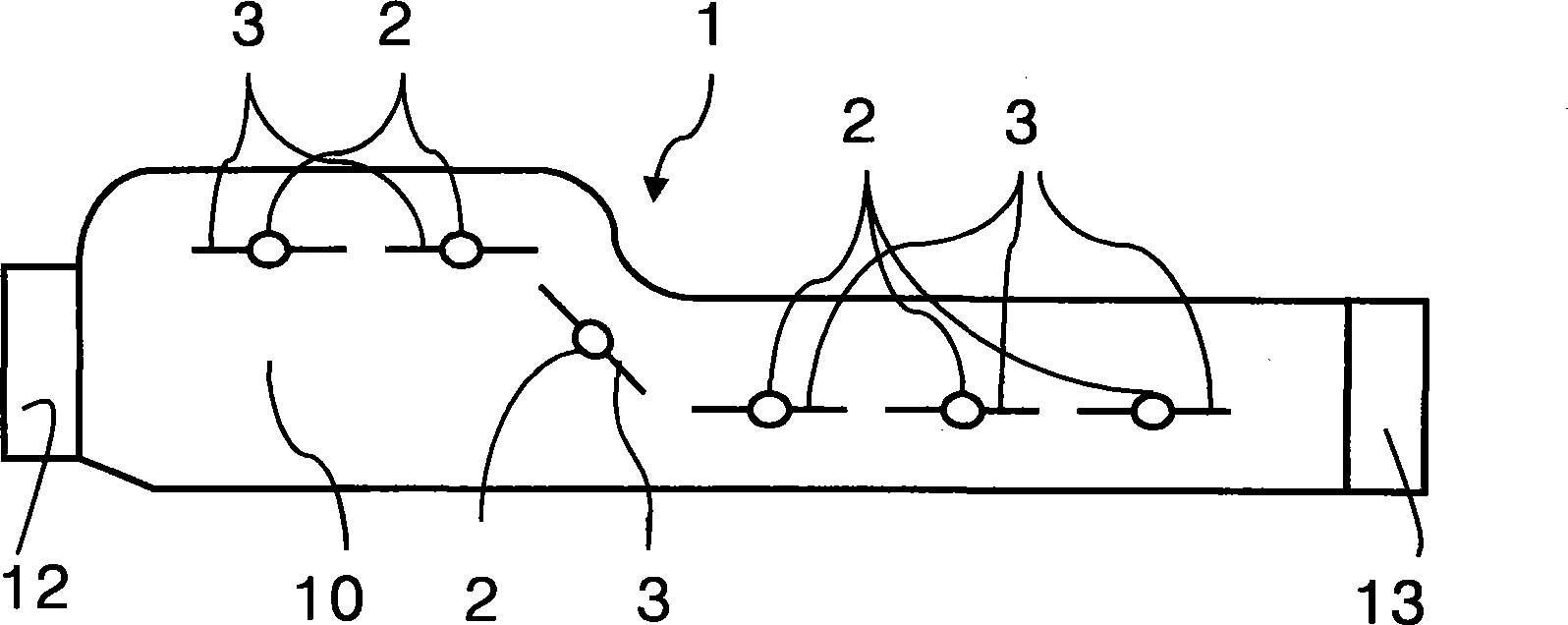
[0059] Unlike the conventional belt-shaped device which needs to be provided with an adhesive layer or a fastener to fix the belt-shaped device, the belt-shaped device 1 of the present invention is fixed by means of gravity. Also see figure 1 and Figure 5 , a weight 5 is connected to the two ends 12 and 13 of the belt-shaped device 1 through a belt body 51 respectively. The weight 5 can be, for example, a bead or other shape of fine particles made by placing a material with a relatively high specific gravity such as lead or steel in a sealed fabric bag, or the belt 51 can be directly bundled with a material with a relatively high specific gravity such as lead or steel. A cylinder made of a large substance. The belt body 51 can be integrally formed with the same material as the belt body 10 . The belt body 51 can also be made of the same or different material as the belt body 10, and is connected to the ends 12 and 13 of the belt body 10 by conventional connection methods s...

no. 2 Embodiment

[0062] In this embodiment, the structure of one of the two end portions 12 and 13 of the belt-shaped device 1 is the same as that of the first embodiment, that is, a weight 5 is connected through a belt body 51 . The difference is that the other end of the two end portions 12 and 13 of the belt-shaped device 1 is pre-fixed on the side of the bed on which the test subject lies by the belt body 51 . The fixing can be a movable connection, for example, the belt body 51 is directly tied to the bed, or the belt 51 and the bed are provided with various locks that can cooperate with each other.

[0063] When using, first place the belt-shaped device 1 on the side that is fixed to the bed, after the subject lies down, pick up the end of the connecting weight 5 and wrap the belt-shaped device 1 around the subject's chest. The other side of the tester is released, allowing the weight 5 to hang down naturally to fix the belt-shaped device 1 on the chest of the test subject.

[0064] Sin...

no. 3 Embodiment

[0066] In this embodiment, the structure of one of the two end portions 12 and 13 of the belt-shaped device 1 is the same as that of the first embodiment, that is, a weight 5 is connected through a belt body 51 . The difference is, see Image 6 In this embodiment, the other end of the two end portions 12 and 13 of the belt-shaped device 1 is connected to a plate body 6 through a belt body 51 .

[0067] When using, let the test subject lie down first, then insert the board body 6 into the test subject's back, and use the pressure exerted by the test subject's body weight to press the board body 6 between the back and the bed. Then, the belt-shaped device 1 is passed around the test subject's chest from one side, and one end of the connecting weight 5 is naturally hung down on the other side to fix the belt-shaped device 1 on the test subject's chest.

[0068] Preferably, the surface of the plate body 6 should not be too smooth, so that the plate body 6 can obtain sufficient fr...


PUM


Abstract

An electrocardiogram measuring electrode holder (1) in the shape of a strap comprises a strap body (10) and two ends (12 and 13). An electrode to be positioned at a predetermined anatomical position about the chest level of a testee is disposed in the strap body (10). At least one of the ends (12 and 13) is connected with a weight (5), so that the strap device (1) is fastened through the weight of the weight (5). Therefore, the ECG (electrocardiogram) measuring electrode holder is simple to fasten and operate.

Description

technical field [0001] In general, the present invention relates to sensors for performing electrocardiographic measurements, and in particular to a harness provided with electrodes, which is operatively simple to fix on the chest of a subject, and the use of said harness The device is an electrocardiograph that acquires electrocardiographic signals and performs electrocardiographic measurements. Background technique [0002] Typically an electrocardiograph (ECG) measurement provides information about the test subject's cardiac function. By placing the sensor on the appropriate part of the subject, the electrodes measure the waveform from the surface of the subject's body and transmit it to, for example, an ECG device, and after magnifying it, display or print out a waveform diagram representing the subject's heart condition to provide Doctors or related professional technicians conduct analysis and diagnosis. [0003] In order to obtain sufficient information to analyze a...

Claims


Application Information

Patent Timeline
IPC IPC(8): A61B5/0408
Inventor 王平段扬徐广忠
Owner 心韵恒安医疗科技(北京)有限公司
Learn More