U-shaped bolt bending device

A bending device and bolt technology, which is applied in the field of hydraulic device manufacturing, can solve problems such as difficult control of the opening angle, asymmetrical lengths on both sides, and inability to achieve precision, etc., to achieve the effects of ensuring strength, solving large errors, and avoiding distortion

Inactive Publication Date: 2013-07-10
舒恒管夹制造有限公司
View PDF6 Cites 23 Cited by
  • Summary
  • Abstract
  • Description
  • Claims
  • Application Information

AI Technical Summary

Problems solved by technology

[0003] The object of the present invention is to provide a U-shaped bolt bending device. Arrange the anti-wheel and the coil wheel on the working platform, fix the straight stud bolts between the anti-wheel and the coil wheel, and make the anti-wheel surround the disc through the transmission device. The center of the wire wheel rotates, and when the anti-wheel rotates, the linear bolt is squeezed to make it bend and deform around the wire wheel, and the limit switch is used to control the opening angle of the bolt to solve the asymmetrical length of the two sides encountered in the bending process of the U-shaped bolt. The opening angle is not easy to control, distortion, thread damage, and the inability to realize mass production of U-shaped bolts with high precision and small error

Method used


Image

  • U-shaped bolt bending device
  • U-shaped bolt bending device
  • U-shaped bolt bending device

Examples


Embodiment Construction

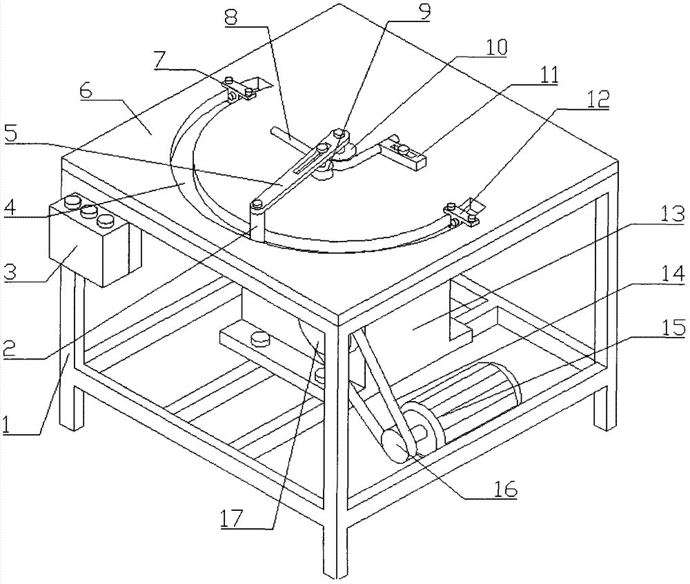
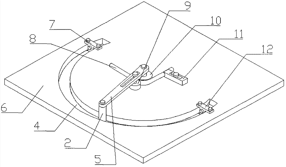
[0041] 1. Determine the type of U-shaped bolt to be processed, select the type of the coil wire wheel 10 and fix it, adjust the workpiece fixing ejector rod 11, select a suitable angle and length and fix it, and place the straight bolt on the coil wire wheel 10 and the anti-wheel 9 In the middle, one end is placed in the groove of the workpiece fixing push rod 11, and the position of the anti-wheel 9 is adjusted so that the workpiece 8 is fixed under the positioning of the anti-wheel 9, the wire coil wheel 10 and the workpiece fixing push rod 11, and the anti-wheel 9 is fixed. Adjust the position of the limit contact reverse switch 7 and the limit contact stop switch 12, select the angle according to the processing requirements, determine the position of the limit switch slider and tighten the bolts at both ends of the slider to fix it.

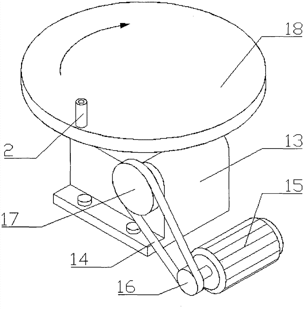
[0042]2. Turn on the power, press the controller 3, the U-shaped bolt bending device starts to work, the motor 15 drives the worm gear reduce...


PUM


Abstract

A U-shaped bolt bending device comprises a bending platform, a control box, a motor, a speed reducer and a bracket, wherein the control box is placed on one side of a frame and is provided with three control switches, namely a positive button, a negative button and a stop button; the negative button is connected with a limit contact negative switch at the terminal end of a circular ring guide slot through a leading wire; and the stop button is connected with a limit contact stop switch at the initial end of the circular ring guide slot through a leading wire. A resistance wheel and a wire coiling wheel are arranged on an operating platform, a linear stud is fixed between the resistance bolt and the wire coiling wheel, the resistance wheel is enabled to rotate around the center of the wire coiling wheel through a transmission device, when the resistance wheel rotates, the linear stud is extruded to enable the wire coiling wheel to be bent and deformed, and the opening angle of the stud is controlled by a limit switch, so as to solve the problems that during the U-shaped bolt bending process, the lengths of the two sides of the bolt is asymmetrical, the opening angle is not easy to control, the two sides of the bolt are twisted, threads are damaged, and the U-shaped bolts cannot achieve high-precision and small-error large batch production.

Description

technical field [0001] The invention relates to the field of hydraulic device manufacturing, in particular to a U-shaped bolt bending device, which is especially suitable for manufacturing and processing U-shaped bolts in high-pressure U-shaped pipe clamps. Background technique [0002] In recent years, due to the rapid development of the automobile industry, pipe fixing fixtures, agricultural machinery products and other industries, the demand for U-shaped bolts is also increasing, and there are more and more varieties and specifications of U-shaped bolts. Therefore, various bolt bending methods and equipment have appeared one after another, but all kinds of bending devices have some disadvantages. The main disadvantages are as follows: (1) The length of the two sides is asymmetrical; (2) The opening angle of the U-shaped bolt cannot be controlled. (3) distortion occurs on both sides, which affects the bolt strength; (4) thread damage, meanwhile, the conventional U-shaped b...

Claims


Application Information

Patent Timeline
IPC IPC(8): B21F1/00
Inventor 王亚军
Owner 舒恒管夹制造有限公司
Why Eureka
Try Eureka