Placing method for girder guiding machine before first hole box girder erection by integrated transportation and erection type bridge girder erection machine

An integrated bridge erecting machine technology, which is applied in erecting/assembling bridges, bridges, bridge construction, etc., can solve the problems of high construction cost, low construction efficiency, and complicated operation, shorten the preparation time for erecting beams, and improve construction efficiency , the effect of simple operation

Active Publication Date: 2013-07-10
中铁十七局集团第三工程有限公司
View PDF4 Cites 12 Cited by
  • Summary
  • Abstract
  • Description
  • Claims
  • Application Information

AI Technical Summary

Problems solved by technology

[0002] The bridge erecting machine is an indispensable construction machine in bridge erection. With the development of modern construction, it is imperative to build large bridges. The existing bridge erecting machine has multiple pillars and legs. When erecting and passing holes Alternate operation, such a structure not only has low construction efficiency and long working cycle, but also requires more auxiliary equipment, and the overall construction cost is high, especially when erecting the first hole and the last hole, the operation is complicated and the work efficiency is low

Method used


Image

  • Placing method for girder guiding machine before first hole box girder erection by integrated transportation and erection type bridge girder erection machine
  • Placing method for girder guiding machine before first hole box girder erection by integrated transportation and erection type bridge girder erection machine
  • Placing method for girder guiding machine before first hole box girder erection by integrated transportation and erection type bridge girder erection machine

Examples


Embodiment Construction

[0027] The present invention will be further described in detail below in conjunction with the accompanying drawings and specific embodiments.

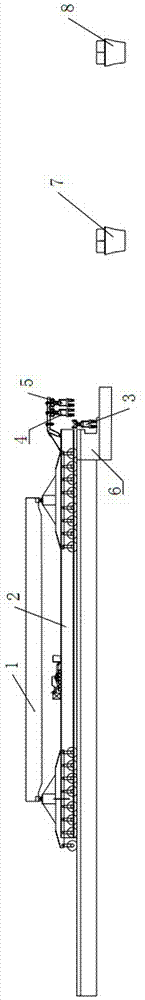
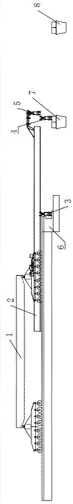
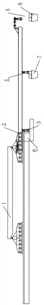
[0028] To sum up, the present invention discloses a method for positioning the front guide girder machine of the first-hole box girder erected by a frame-transporting integrated bridge erecting machine, which is characterized in that it includes the following steps:

[0029] The first step: Lifting beam machine 1 and lifting guide beam machine 2 in place (see figure 1 ), the front end of the beam guide machine 2 is flush with the inner side of the abutment; the first step includes placing the auxiliary rollers of the beam guide machine 2 on the bridge surface in advance, and placing the 4 pads of the auxiliary rollers on the abutment 6 in advance, as Support the use of rear roller outrigger 3;

[0030] Step 2: Rear roller outrigger 3 is in place (refer to figure 1 ), lower the rear roller outrigger 3 to the abutment 6, jack up, leve...


PUM


Abstract

The invention discloses a placing method for a girder guiding machine before first box hole girder erection of a transportation and erection integrated bridge girder erection machine and relates to the technical field of a special method or device for erection or assembly of bridges. The method comprises the following steps: firstly, a girder hoisting machine hoists the girder guiding machine in place; secondly, a rear roller support leg is arranged in place; thirdly, a middle roller support leg is arranged in place; fourthly, a front roller support leg is arranged in place; fifthly, a rear support leg is arranged in place; and sixthly, the middle roller support leg and the rear roller support leg are shifted, and the girder guiding machine is arranged in place. The method has the advantages that support functions of the front roller support leg, the middle roller support leg and the rear roller support leg are fully used, the girder guiding machine is arranged in place before the girder hoisting machine erects the first hole box girder, and any auxiliary devices are not required; and the whole process is simple to operate and short in consumed time, preparation time for bridge erection can be shortened greatly, time is fought for formal box girder erection, and the construction efficiency is improved.

Description

technical field [0001] The invention relates to the technical field of methods or equipment specially used for erecting or assembling bridges, in particular to a method for positioning a leading girder machine before erecting a first-hole box girder with a frame-transporting integrated bridge erecting machine. Background technique [0002] Bridge erecting machine is an indispensable construction machine in bridge erection. With the development of modern construction, it is imperative to build large bridges. The existing bridge erecting machine has multiple pillars and legs. When erecting and passing holes Alternate operation, such a structure not only has low construction efficiency and long working cycle, but also requires more auxiliary equipment, and the overall construction cost is high, especially when erecting the first hole and the last hole, the operation is complicated and the work efficiency is low. Contents of the invention [0003] The technical problem to be s...

Claims


Application Information

Patent Timeline
Patent Type & Authority Applications(China)
IPC IPC(8): E01D21/00
Inventor 乐锋杨新明魏文柱曹三明张生全景俊锋郭宏坤
Owner 中铁十七局集团第三工程有限公司
Why Eureka
Try Eureka