Blade type pneumatic motor with variable expansion ratio

A technology of air motor and expansion ratio, which is applied to rotary piston engines, engine components, machines/engines, etc., can solve the problem of not being able to ensure the full expansion of the working medium in real time, reducing the energy conversion efficiency of the compressed working medium, and the lack of ability to control the state of the working medium. and other problems, to achieve the effect of solving the problem of working fluid leakage, low cost and good control

Inactive Publication Date: 2013-07-10
JILIN UNIV
View PDF5 Cites 6 Cited by
  • Summary
  • Abstract
  • Description
  • Claims
  • Application Information

AI Technical Summary

Problems solved by technology

[0004] However, due to the relatively fixed positions of the main exhaust hole and the air intake hole in the existing vane-type air motor, the expansion ratio of the motor is fixed. When the intake air is ideal air with different temperatures and pressures, it is impossible to ensure sufficient expansion of the working medium in real time and effectively prevent Overexpansion of the working fluid; when the intake air is a phase-change working fluid with different temperatures and pressures, the expansion ratio cannot be changed in real time according to the characteristics of the working fluid, and the ability to control the state of the working fluid is lacking
The fixed expansion ratio makes a single air motor only suitable for a specific range of working conditions, and the adjustment of torque and other related aspects through peripherals will increase the complexity of the mechanism and cause a decrease in conversion efficiency
In addition, most of the current vane-type air motors have an inscribed fit between the inner rotor and the outer stator to achieve the maximum eccentricity and maximize the output power of the motor. However, when the protruding area of ​​the vane increases, it will produce The sealing problem between the blade and the stator causes increased internal leakage and reduces the energy conversion efficiency of the compressed working fluid

Method used


Image

  • Blade type pneumatic motor with variable expansion ratio
  • Blade type pneumatic motor with variable expansion ratio
  • Blade type pneumatic motor with variable expansion ratio

Examples


Embodiment Construction

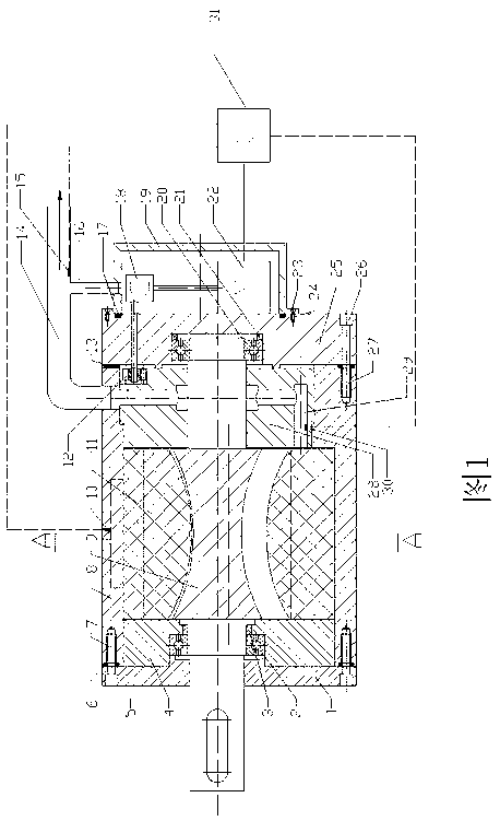
[0016] Below in conjunction with accompanying drawing, technical scheme of the present invention is described in further detail:

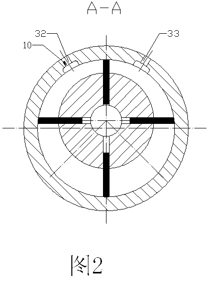
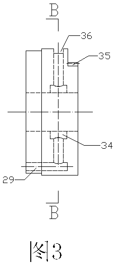
[0017] Such as figure 1 As shown, the present invention consists of front machine cover 1, bearing I2, bushing 3, front end cover 4, bolt I5, gasket I6, internal thread I7, stator 8, rotor 9, temperature and pressure sensor I10, blade 11, drive gear 12 , Gasket II13, main exhaust duct 14, temperature and pressure sensor II15, leakage working fluid return channel 16, gasket III17, gear box 18, drive mechanism sealing shell 19, bearing II20, thrust ring 21, drive motor 22, bolts Ⅱ23, internal thread Ⅱ24, rear machine cover 25, bolt Ⅲ26, internal thread Ⅲ27, main exhaust hole rotatable rear end cover 28, main exhaust hole 29, temperature and pressure sensor Ⅲ30, controller 31.

[0018] Among them, the stator 8 and the rotor 9 are non-inscribed and eccentrically arranged to reduce the protruding area of ​​the blades and reduce the internal leakage of ...


PUM


Abstract

The invention provides a blade type pneumatic motor with a variable expansion ratio. The blade type pneumatic motor comprises a front machine cover, a rear machine cover, a front end cover, a main exhaust hole rotation rear end cover, a rotor, a stator, a blade and a driving mechanism seal housing; a main exhaust hole, an inner ring groove, a top groove and a driven gear are machined on the main exhaust hole rotation rear end cover; the rotor and the stator are eccentrically arranged in an non-internally tangent manner; and a driving mechanism on the rear machine cover is packaged by the driving mechanism seal housing. According to practical requirements, under the driving of the driving mechanism, the volume at the moment of expansion is changed through the change of the position of the main exhaust hole, so that the variable adjustment of the expansion ratio is realized; and simultaneously, the external leakage of a working medium is alleviated through a leakage working medium backflow passage. The system is simple in structure and convenient to process.

Description

technical field [0001] The invention belongs to the category of pneumatic motors in the technical field of machinery, and in particular relates to a vane-type pneumatic motor with variable expansion ratio. Background technique [0002] The vane air motor is a prime mover with compressed working fluid as the power source. It is a device that converts pressure energy into mechanical energy by using the expansion of compressed working fluid. It generally has a casing, a machine cover, a stator, a rotor, blades, front and rear It is composed of end cover, bearing, bushing, thrust ring and other parts. A working chamber is formed between the stator and the rotor. After the compressed working fluid enters the working chamber, the pressure can generate torque on the blades to make the rotor rotate and do work. [0003] The existing vane-type air motors basically have a sliding vane eccentric structure, and two protruding air holes are provided at the minimum distance between the mo...

Claims


Application Information

Patent Timeline
Patent Type & Authority Applications(China)
IPC IPC(8): F01C1/344F01C21/18F01C20/10F01C19/00F01C19/12
Inventor 韩永强康见见柴嘉鸿许允田径
Owner JILIN UNIV
Why Eureka
Try Eureka