
Earthquake-isolation energy dissipator for ultra-high-voltage converter transformer

A converter transformer and energy dissipation device technology, which is applied in the fields of earthquake resistance, shock resistance and isolation, can solve the problems of converter transformer fire, bushing damage, large acceleration, etc., and achieves the effects of simple construction and installation, low cost and stable performance.

Active Publication Date: 2013-07-10
CENT SOUTHERN CHINA ELECTRIC POWER DESIGN INST CHINA POWER ENG CONSULTING GROUP CORP
View PDF7 Cites 5 Cited by
  • Summary
  • Abstract
  • Description
  • Claims
  • Application Information

AI Technical Summary

Problems solved by technology

The traditional anti-seismic method is to increase the strength and rigidity of the equipment to resist the earthquake. Under the earthquake, this method may be damaged under the fortification intensity, but it will inevitably cause the converter transformer body to be damaged under the fortification intensity. Faults caused by overturning, sliding, distance changes between the fuel tank and the body, fire or bushing damage, and at the same time, due to the relatively large acceleration, it is easy to cause the fire of the converter transformer

Method used


Image

  • Earthquake-isolation energy dissipator for ultra-high-voltage converter transformer
  • Earthquake-isolation energy dissipator for ultra-high-voltage converter transformer
  • Earthquake-isolation energy dissipator for ultra-high-voltage converter transformer

Examples


Embodiment Construction

[0021] The present invention will be further described in detail below in conjunction with the accompanying drawings and specific embodiments.

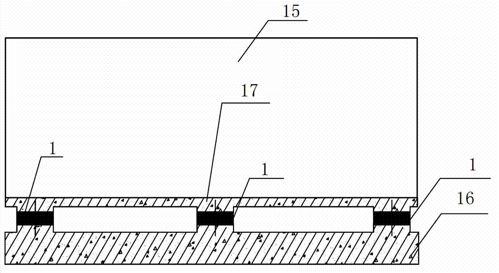
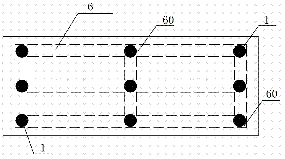
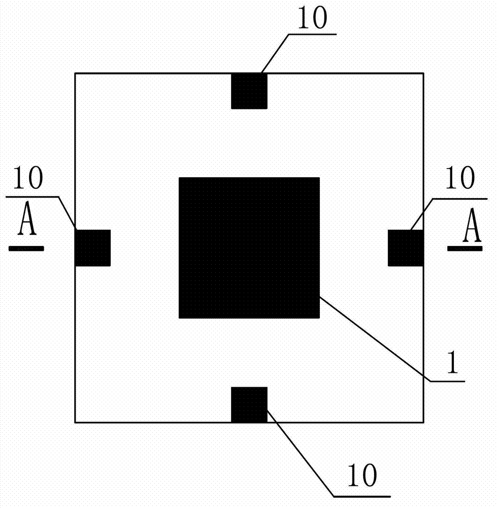
[0022] Such as Figure 1~2 The shock isolation and energy dissipation device for the UHV converter transformer shown includes a plurality of shock isolation supports 1. The shock isolation supports 1 are provided with horizontally arranged steel plates 2 and thin rubber layers 3 at intervals from top to bottom. The shock isolation supports 1 There is a central hole 4 in the center of the center hole 4, and a lead core 5 is arranged in the central hole 4. It is characterized in that: a "Tian"-shaped basic valve plate 6 composed of steel beams is also provided, and multiple shock-isolation supports 1 are installed on the basic valve plate. On the steel beam node 60 of 6; also be provided with the upper connection plate 7 and the lower connection plate 8 parallel up and down, the upper and lower sides of the shock-isolation bearing 1 are...


PUM


Abstract

The invention discloses an earthquake-isolation energy dissipator for an ultra-high-voltage converter transformer. The earthquake-isolation energy dissipator comprises a plurality of earthquake-isolation supports, steel plates and thin rubbers which are arranged horizontally are arranged on the earthquake-isolation supports from top to bottom at intervals, and central holes are arranged at centers of the earthquake-isolation supports and provided with lead cores inside. The earthquake-isolation energy dissipator is characterized by further being provided with a squared foundation valve plate composed by steel beams, an upper connecting plate and a lower connecting plate, wherein the plurality of earthquake-isolation supports are installed at steel beam nodes of the foundation valve plate, the upper connecting plate and the lower connecting plate are parallel, and the upper and lower surfaces of the earthquake-isolation supports are connected with the centers of the upper connecting plate and the lower connecting plate respectively. According to the earthquake-isolation energy dissipator, the stability is guaranteed, simultaneously, the horizontal stiffness is small, the earthquake-isolation damping effect can be improved, soft limiting and anti-falling functions are provided, the safety of the earthquake-isolation energy dissipator under the action of earthquakes can be guaranteed, when the earthquake-isolation fails, a certain damping effect is also provided, and the safety function is provided in case of failure. The earthquake-isolation energy dissipator is low in construction cost, simple in construction and provided with good social benefits.

Description

technical field [0001] The invention relates to the field of anti-shock, anti-shock, and shock-isolation technologies for buildings, structures, and equipment, in particular to a shock-isolation and energy-dissipating device for an ultra-high voltage converter transformer. Background technique [0002] The converter transformer is the core electrical equipment in the DC transmission project. The converter transformer has the characteristics of large volume and high quality, and the porcelain bushing is long. Earthquake force and displacement, causing damage to the converter transformer, threatening the operation safety of the converter transformer, directly causing major economic losses, and more importantly, causing indirect major economic losses and casualties, such as affecting earthquake relief after the earthquake work and produce secondary disasters. Through the investigation of many major earthquake disasters at home and abroad, there have been many substation main t...

Claims


Application Information

Patent Timeline
Patent Type & Authority Applications(China)
IPC IPC(8): F16F7/108F16F1/40
Inventor 陈传新陈寅陈俊吴必华陈一军张华郑威刘素丽
Owner CENT SOUTHERN CHINA ELECTRIC POWER DESIGN INST CHINA POWER ENG CONSULTING GROUP CORP
Learn More