Automatic calibration method for video monitoring system

A video monitoring system and automatic calibration technology, which is applied in closed-circuit television systems, image data processing, instruments, etc., can solve the problems of positioning accuracy, limitations, and cumbersome processes

Active Publication Date: 2013-07-10
AQUILLANETWORKTECH
View PDF2 Cites 44 Cited by
  • Summary
  • Abstract
  • Description
  • Claims
  • Application Information

AI Technical Summary

Problems solved by technology

[0020] Since the calibration process needs to manually control the rotation of the ball machine, the process is cumbersome and the positioning accuracy is affected and limited by the operator

Method used


Image

  • Automatic calibration method for video monitoring system
  • Automatic calibration method for video monitoring system
  • Automatic calibration method for video monitoring system

Examples


Embodiment Construction

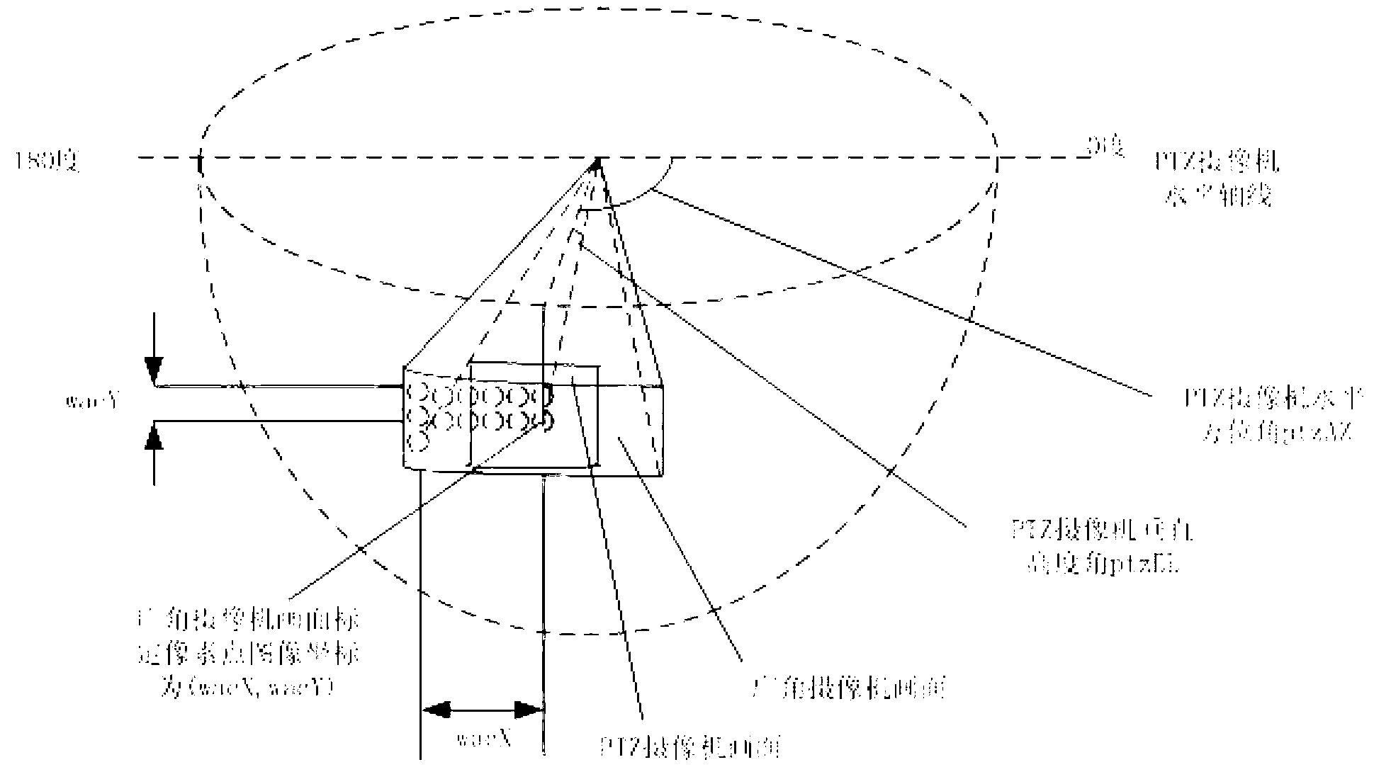
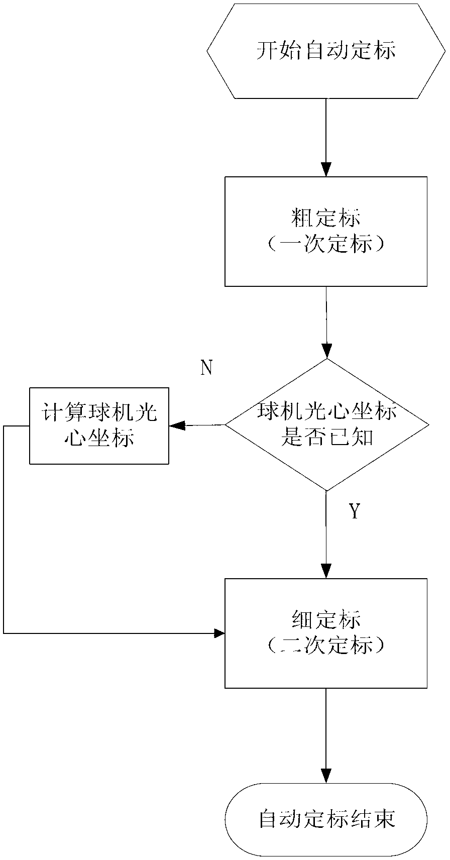
[0062] As mentioned above, the purpose of automatic calibration is to automatically establish the mapping relationship between the image coordinates of the gun camera and the physical coordinates of the dome camera. Such as figure 2 As shown, the preferred steps of the automatic calibration method of the present invention include: a rough calibration (primary calibration) step, a step of calculating the optical center image coordinates of the ball machine, and a fine calibration (secondary calibration) step, thereby completing the automatic target.

[0063] Each of the above steps will be described in detail below in conjunction with the accompanying drawings.

[0064] Coarse calibration (primary calibration) steps:

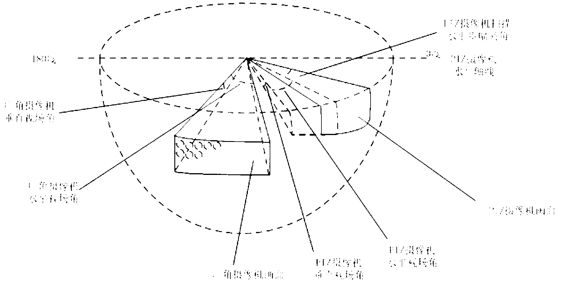
[0065] Such as image 3 As shown, since the relationship between the physical coordinates of the gun camera and the dome camera is not known at the beginning, the dome camera is controlled at a certain magnification, such as 1X magnification, and automaticall...


PUM


Abstract

The invention provides an automatic calibration method for a video monitoring system. The video monitoring system comprises a wide-angled camera namely a gun-type camera and a PTZ camera namely a ball-type camera, wherein the wide-angled camera is used for shooting a wide angled picture namely a gun-type camera picture in a large-scale field of vision, and the PTZ camera is used for shooting a local enlarged picture namely a ball-type camera picture in the large-scale field of vision. The automatic calibration method comprises a step of rough calibration and a step of specific calibration, wherein the rough calibration is that a mapping relation between a gun-type camera picture coordinate and a ball-type camera picture coordinate and a mapping relation between the ball-type camera picture coordinate and a ball-type physics coordinate are utilized to obtain a mapping relation between the gun-type camera picture and the ball-type physics coordinate, and the specific calibration is that a rough calibration result is rectified by utilizing of a ball-type light center picture coordinate. By means of the automatic calibration method, people can be liberated from a complex calibration operation, and automation of a procedure is achieved. The whole calibration time is controlled within 90s equal to the calibration time of a skillful operator, and the calibration precision is even superior to that of manual calibration.

Description

technical field [0001] The invention relates to an automatic calibration method, in particular to an automatic calibration method used in a video monitoring system. Background technique [0002] In the process of video surveillance, it is hoped to obtain a clear image of the target. Using wide-angle cameras and PTZ cameras alone has its own defects. Due to the limited resolution of wide-angle cameras, the ability to obtain details in local areas is relatively poor; although PTZ cameras can obtain clearer details, the monitoring range is greatly limited due to the smaller field of view. [0003] In view of this, a wide-angle camera and a PTZ camera linkage control method and device (hereinafter referred to as "gun ball linkage control system") are used for monitoring. Use the wide-angle camera (hereinafter referred to as "the camera") to monitor a wide range of scenes, and at the same time control the PTZ camera (hereinafter referred to as the "ball camera") to obtain local...

Claims


Application Information

Patent Timeline
Patent Type & Authority Applications(China)
IPC IPC(8): G06T7/00H04N7/18
Inventor 刘玉平袁肇飞
Owner AQUILLANETWORKTECH
Why Eureka
Try Eureka