Spherical liquid-crystal laser

A technology of lasers and liquid crystals, applied in lasers, parts of liquid lasers, parts of lasers, etc., can solve problems such as high temperature sensitivity

Active Publication Date: 2013-07-10
INSTITUT JOZEF STEFAN
View PDF3 Cites 18 Cited by
  • Summary
  • Abstract
  • Description
  • Claims
  • Application Information

AI Technical Summary

Problems solved by technology

A technical disadvantage of the proposed spherical laser is therefore the high temperature sensitivity of the amplitude of the stimulated emission of spherical resonators with surface reflectors, which is caused by the temperature elongation of the resonator

Method used


Image

  • Spherical liquid-crystal laser
  • Spherical liquid-crystal laser
  • Spherical liquid-crystal laser

Examples


Embodiment Construction

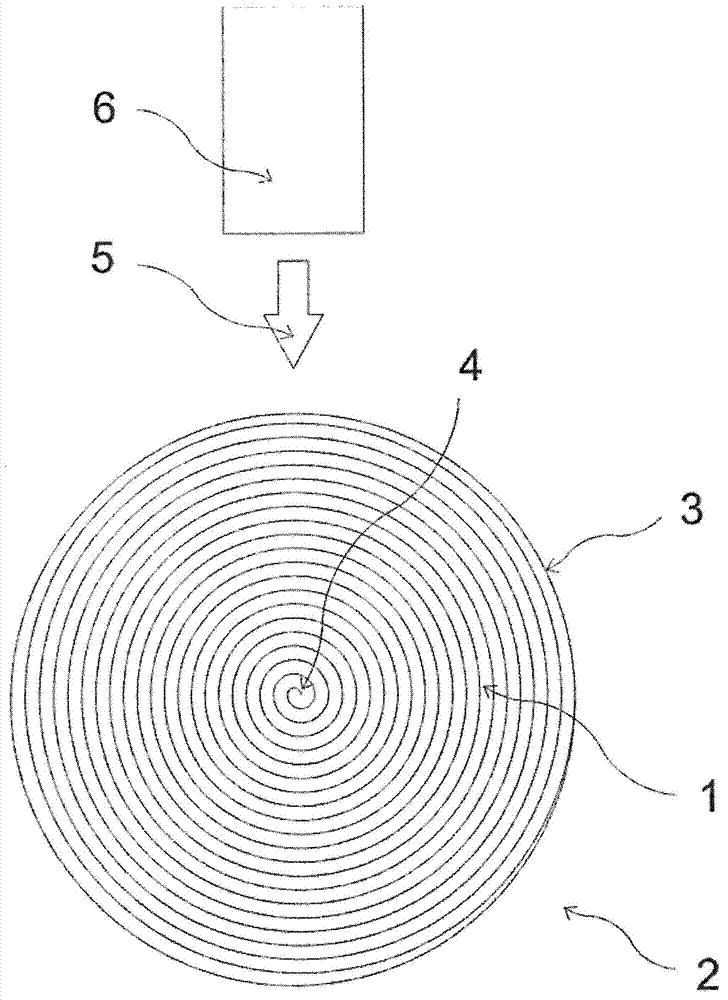
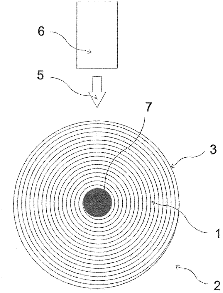
[0030] figure 1 A substantially spherical liquid crystal laser common to all presented variants is schematically shown. The spherical liquid crystal laser is fabricated in the shape of a droplet with helically arranged liquid crystals 1 placed in a transparent outer medium 2 with a sharp optical boundary 3 between these two elements. Due to the surface tension, the droplet of cholesteric liquid crystal is shaped as a complete spherical droplet in the external liquid medium. The droplet size is preferably in the range between a few nanometers and 100 μm. Droplets may be formed by mechanical mixing of liquid crystals and an external liquid medium or by well-known phase separation procedures during polymerization or photopolymerization of a supporting optically isotropic medium in which liquid crystal droplets are distributed.

[0031] The boundary between the external substance and the inside of the droplet is formed in such a way that the liquid crystal molecules at the bound...


PUM


Abstract

The patent refers to one or more droplets of chiral liquid crystals used as point source(s) of laser light. The source is shaped as a droplet of chiral liquid crystals (1) and an active medium preferably dispersed in the liquid crystals. The source is spherical and with a size of preferably between a few nanometres and 100 micrometres. A droplet consists of chiral liquid crystals (1) that have selective reflection in the range of the active medium's emission and can be cholesteric liquid crystals, a mixture of nematic liquid crystals and a chiral dopant or any other chiral liquid-crystal phase, preferably the blue phase, the ferroelectric phase, the antiferroelectric phase, any of the ferrielectric phases or another chiral phase of a soft substance, that need not be chiral by itself.

Description

technical field [0001] The invention finds use in the field of producing lasers, more particularly dye lasers. Background technique [0002] Modern technologies for the production of microelectronic and optoelectronic circuits allow the efficient production of tiny lasers. Diode semiconductor microlasers are especially known because they are the most commonly used type of laser. When electricity is applied, the thin layer around the semiconducting p-n junction acts as an active medium that emits light. This active lasing region must be within a resonant cavity, which can be fabricated in several different ways. In terms of the type of resonator, the main types of semiconductor lasers are Fabry-Pérot, DFB and VCSEL. [0003] Fabry-Pérot lasers are the simplest and by far the most widely used. Its resonant cavity is made by breaking the semiconductor crystal containing the p-n junction on both sides and along the crystal structure. In this way, two perfectly flat parallel...

Claims


Application Information

Patent Timeline
Patent Type & Authority Applications(China)
IPC IPC(8): H01S3/06H01S3/16H01S3/102
CPCH01S3/0627H01S3/1028H01S3/1053H01S3/1065H01S3/1686H01S3/06H01S3/102H01S3/16H01S3/022
Inventor I·穆塞维奇M·胡马尔
Owner INSTITUT JOZEF STEFAN
Why Eureka
Try Eureka