Bead positioning and clamping platform of bead winding machine

A traveler winding machine, positioning and clamping technology, which is applied in the direction of making rings from wires, other household appliances, household appliances, etc., can solve the problems of the complicated structure of the traveler positioning device, the inability to adapt to the traveler winding, and the inability to guarantee the winding tension. , to achieve the effect of low installation and positioning accuracy requirements, simple structure and low vibration

Active Publication Date: 2013-07-17
哈尔滨工大宏图橡塑科技有限公司
View PDF6 Cites 3 Cited by
  • Summary
  • Abstract
  • Description
  • Claims
  • Application Information

AI Technical Summary

Problems solved by technology

[0002] The structure of the traveler positioning device of the existing traveler winding machine is complicated, and the production cost is relatively high
Due to the large diameter (φ1.5mm-φ2.2mm) of the steel wire wound by the aviation tire traveler, the clamping and fixing device of the conventional traveler winding machine is slightly less stable, and there is a large vibration when winding such a diameter of steel wire, and it is even difficult to Guaranteed smooth winding, but cannot guarantee a large enough winding tension during winding, thus affecting the winding accuracy; the specification of the bead positioning device is fixed, and cannot be adapted to the winding of bead rings of different specifications

Method used


Image

  • Bead positioning and clamping platform of bead winding machine
  • Bead positioning and clamping platform of bead winding machine
  • Bead positioning and clamping platform of bead winding machine

Examples


Embodiment Construction

[0012] The present invention will be described in further detail below in conjunction with the accompanying drawings: the present embodiment is implemented on the premise of the technical solution of the present invention, and detailed implementation is provided, but the protection scope of the present invention is not limited to the following embodiments.

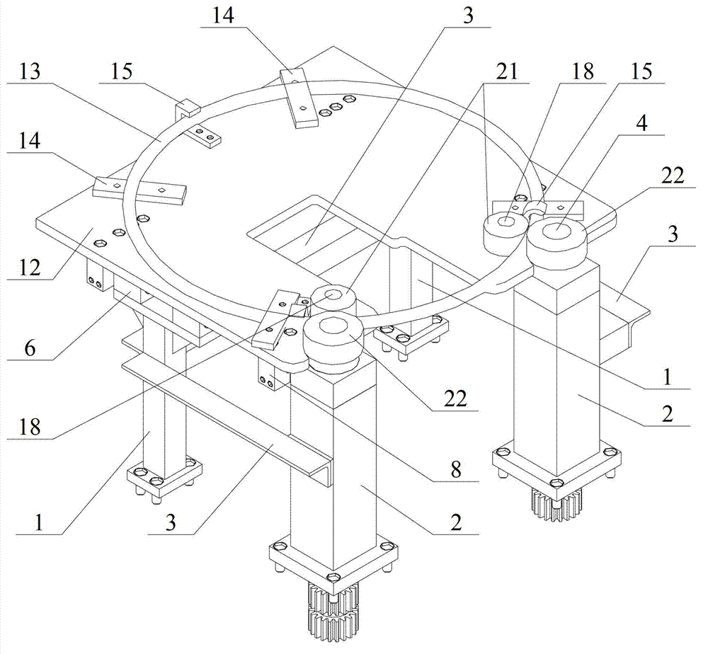
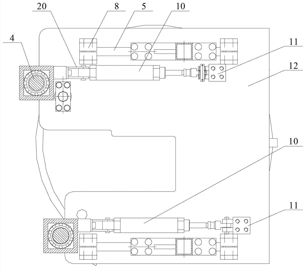
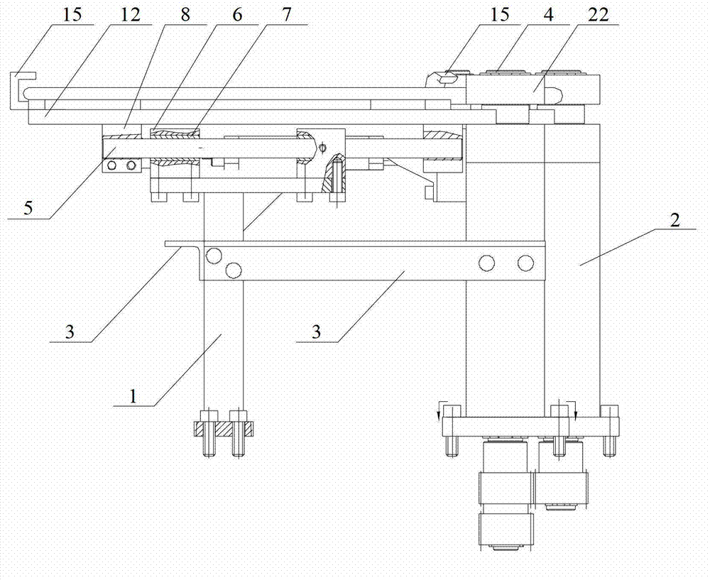
[0013] like Figure 1 to Figure 5 As shown, the traveler positioning and clamping platform of a traveler winding machine involved in this example includes a pair of platform guide rail pillars 1, a pair of steel ring driving columns 2, three platform fixed equilateral angle steels 3, and two steel rings Drive shaft 4, two platform guide rails 5, four platform guide rail sliders 6, four platform guide rail copper sleeves 7, four platform guide rail end seats 8, two cylinders 10, two air cylinder end seats 11, working platform 12, Four platform gaskets 14, three steel ring pressing blocks 15, two driven drive roller shafts 1...


PUM


Abstract

The invention provides a bead positioning and clamping platform of a bead winding machine. A pair of platform guide pillars and a pair of bead driving uprights are vertically fixed below an operating platform. Two ends of a fixed equilateral steel angle of the platform are connected to the platform guide pillars and the bead driving uprights respectively. Two platform guide sliders are fixed at the upper end of each platform guide pillar. A platform guide copper sleeve is inset in an inner hole of each platform guide slider. After gas is introduced into cylinders, the cylinders drive the operating platform to move through platform guides, so that a driven shaft roller sleeve, a bead core and a bead driving shaft roller sleeve are contacted with one another and compressed, the bead core is held, a bead driving shaft is driven, and the bead core is driven to rotate by friction between the driven shaft roller sleeve and the bead driving shaft roller sleeve. The requirement on bead fitting and positioning precision is low, a platform pad and a bead pressure block on the operating platform need not be demounted repeatedly, and accordingly clamping is easy, operating is simple and efficiency is higher.

Description

technical field [0001] The invention relates to a bead ring positioning and clamping platform of a bead ring winding machine, belonging to the technical field of clamping platforms. Background technique [0002] The structure of the traveler positioning device of the existing traveler winding machine is complicated, and the production cost is relatively high. Due to the large diameter (φ1.5mm-φ2.2mm) of the steel wire wound by the aviation tire traveler, the clamping and fixing device of the conventional traveler winding machine is slightly less stable, and there is a large vibration when winding such a diameter of steel wire, and it is even difficult to Guarantee smooth winding, but cannot guarantee enough winding tension during winding, thus affecting the winding accuracy; the specification of the bead positioning device is fixed, and cannot adapt to the winding of bead rings of different specifications. The clamping device of the present invention has high strength and c...

Claims


Application Information

Patent Timeline
Patent Type & Authority Applications(China)
IPC IPC(8): B21F37/00
Inventor 陈家轩卢礼华
Owner 哈尔滨工大宏图橡塑科技有限公司
Why Eureka
Try Eureka