Processing apparatus, tool, processing method, and method for setting processing position

A processing device and processing position technology, applied in the direction of manufacturing tools, metal processing, glass cutting devices, etc., can solve the problems of difficult semiconductor wafer shooting, difficult to accurately obtain the processing position, etc., and achieve the effect of accurate processing position

Inactive Publication Date: 2013-07-17
YASKAWA DENKI KK
View PDF5 Cites 5 Cited by
  • Summary
  • Abstract
  • Description
  • Claims
  • Application Information

AI Technical Summary

Problems solved by technology

[0004] However, in the sheet cutting device described in the aforementioned Japanese Patent Laid-Open No. 2007-288010, the processing position of the protruding portion is determined based on the image data captured by the camera, so that

Method used


Image

  • Processing apparatus, tool, processing method, and method for setting processing position
  • Processing apparatus, tool, processing method, and method for setting processing position
  • Processing apparatus, tool, processing method, and method for setting processing position

Examples


no. 1 approach )

[0039] First, refer to Figures 1 to 9 The structure of the robot 100 according to the first embodiment will be described. The robot 100 is an example of a "processing device". In other words, robots can include not only figure 1 The articulated robot shown can also include SCARA-type robots and Cartesian-type (Cartesian) robots. In addition, processing tools can be arranged on a gantry with at least three axes perpendicular to each other.

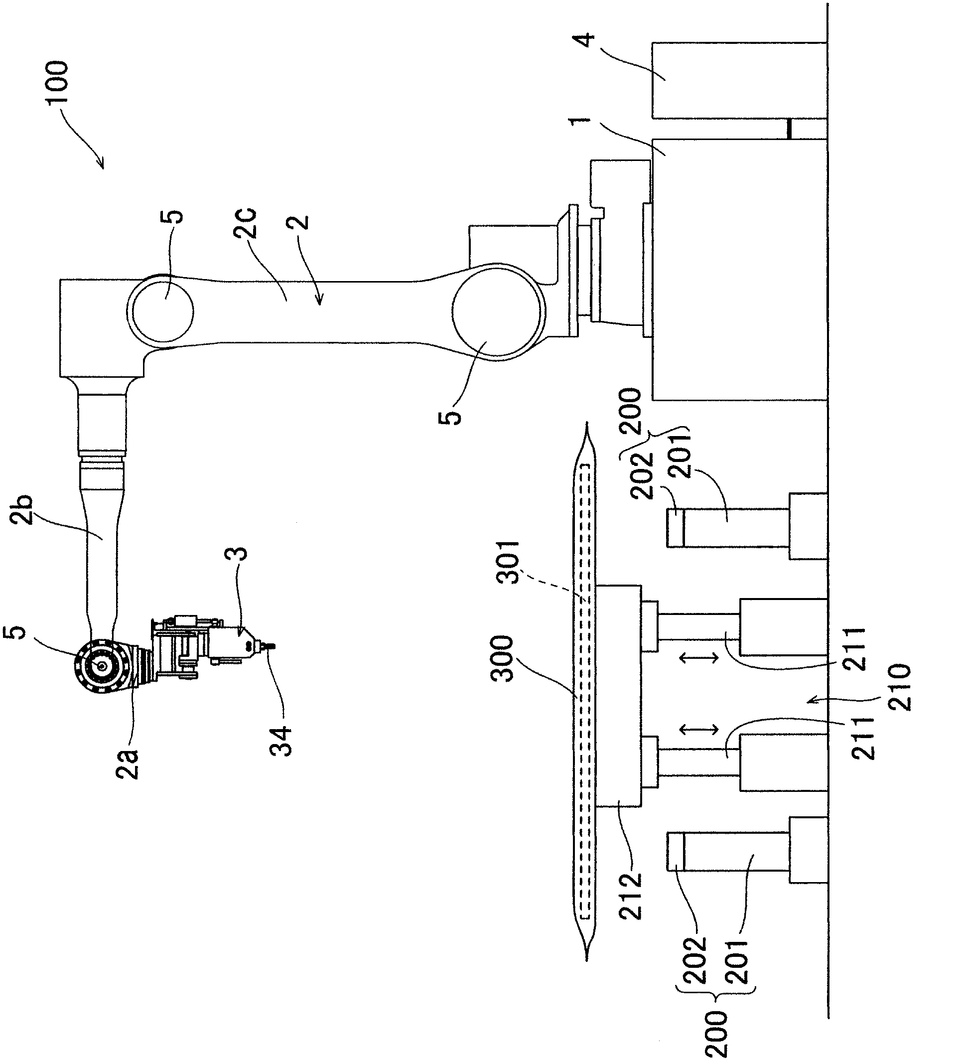
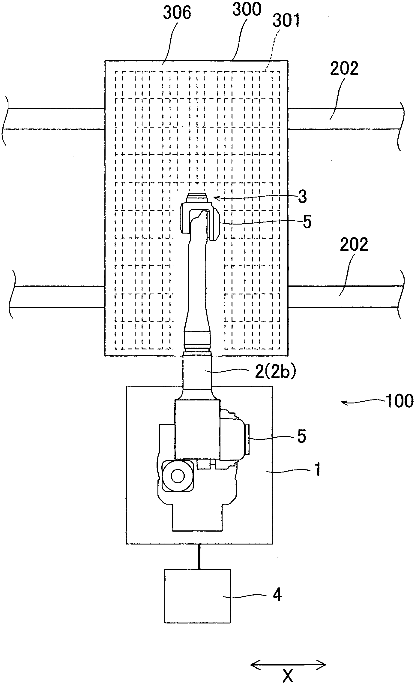
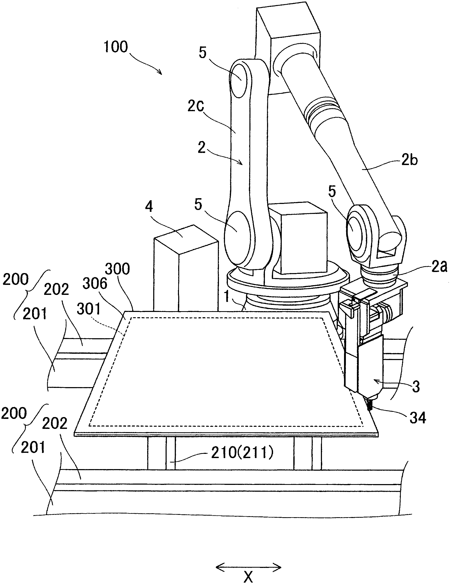
[0040] Such as Figure 1 to Figure 3 As shown, the robot 100 includes a base 1 , a robot arm 2 installed on the base 1 , an end effector 3 installed at the front end of the robot arm 2 , and a robot controller 4 for controlling the overall movement of the robot 100 . A conveyor 200 that transfers the substrate 300 and a mount portion 210 that mounts the substrate 300 when trimming is performed are provided near the robot 100 .

[0041] The conveyor 200 includes a table part 201 and a roller part 202 set on the table part 201 to move th...

no. 2 approach )

[0079] Next, refer to Figure 17 and Figure 18 The end effector 6 according to the second embodiment will be described. In this second embodiment, unlike the above-described first embodiment in which a substantially U-shaped thermal cutter 34 is contained in the end effector 3 , a thermal cutter 64 in the form of a cutter is contained in the end effector 6 . The thermal cutter 64 is an example of a "knife".

[0080] Such as Figure 17As shown, the end effector 6 according to the second embodiment includes an arm mounting part 61 , an air slide 62 , a thermal cutter body 63 and a thermal cutter 64 . The arm mounting portion 61 is fixedly mounted on the arm portion 2 a and located above the air slide 62 . The heat cutter main body 63 is arranged below the air slide table 62 . The thermal cutter blade 64 is attached to the front end of the thermal cutter main body 63 along a direction intersecting the vertical direction (Z direction) at a predetermined angle θ2.

[0081] S...


PUM


Abstract

The present invention relates to a processing apparatus, a tool, a processing method, and a method for setting a processing position. The processing apparatus includes a tool processing a protruding portion of a sheet member covering a base substrate protruding from the base substrate and a control portion mechanically or electrically detecting a position where the tool comes into contact with the base substrate and acquiring a processing position based on the position where the tool comes into contact with the base substrate.

Description

technical field [0001] The invention relates to a processing device, a tool, a processing method and a processing position setting method. Background technique [0002] A processing device (sheet cutting device) including a knife for processing a protruding portion is generally known. [0003] Japanese Patent Laid-Open No. 2007-288010 discloses a sheet cutting device including a robot having a robot arm, a chuck mounted on the front end of the robot arm, a cutting knife held by the chuck, and a blade mounted on the chuck. on the camera. The sheet cutting device is configured to cut, by a cutting blade, a protruding portion of a sheet stuck to protrude from the semiconductor wafer along the outer periphery of the semiconductor wafer. In this sheet cutting device, the cutting (processing) position of the protruding portion by the cutting blade is determined based on the image data of the cutting blade, the sheet, and the semiconductor wafer captured by the camera. [0004] ...

Claims


Application Information

Patent Timeline
IPC IPC(8): B26F3/08B26D5/02B26D7/27C03B33/02
CPCB25J9/1679G05B2219/37405G05B2219/45031
Inventor 下野利昭
Owner YASKAWA DENKI KK
Why Eureka
Try Eureka