Method and device for controlling power supply of double energy sources

A technology of power supply control and dual energy, applied in circuit devices, electric vehicles, electrical components, etc., can solve problems such as inability to pull trains, application limitations of electric locomotives, and affecting the practicability of electric locomotives

Active Publication Date: 2013-07-17
ZHUZHOU ELECTRIC LOCOMOTIVE CO
View PDF5 Cites 28 Cited by
  • Summary
  • Abstract
  • Description
  • Claims
  • Application Information

AI Technical Summary

Problems solved by technology

[0002] At present, electric locomotives are powered by catenary. However, due to the limitation of catenary network layout in practical applications, there will be no catenary section or catenary without electricity during locomotive operation. In any

Method used


Image

  • Method and device for controlling power supply of double energy sources
  • Method and device for controlling power supply of double energy sources
  • Method and device for controlling power supply of double energy sources

Examples


Embodiment 1

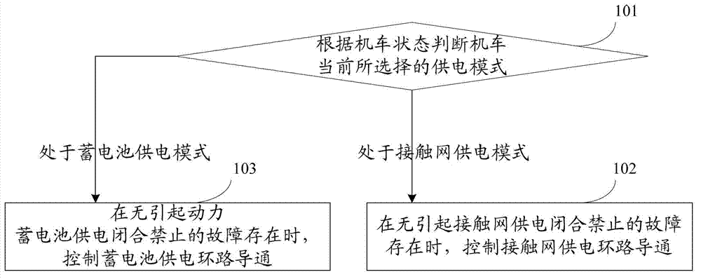
[0041] see figure 1 , which is a method flow chart of a dual-energy power supply control method disclosed in Embodiment 1 of the present application. The method includes the following steps:

[0042] Step 101: judging the power supply mode currently selected by the locomotive according to the state of the locomotive;

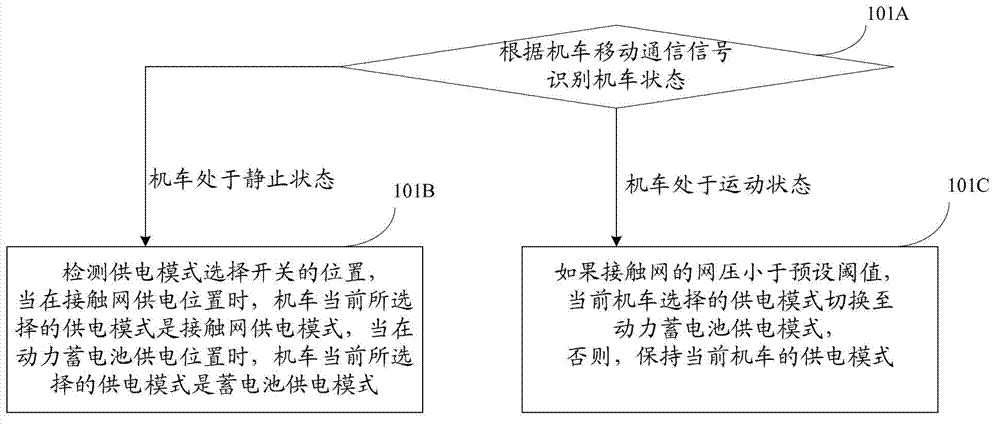
[0043] Preferably, step 101 includes: three small steps 101A-101C, specifically as figure 2 The flow chart of the method for judging the power supply mode currently selected by the locomotive is shown, wherein step 101A: identify the state of the locomotive according to the mobile communication signal of the locomotive;

[0044] The state of the locomotive includes stationary and moving. Generally, the state of the locomotive is judged by the traction control unit according to the speed of the locomotive or the speed of the traction motor, and then transmitted to the central control unit through the mobile communication signal MVB of the locomotive. The centra...

Embodiment 2

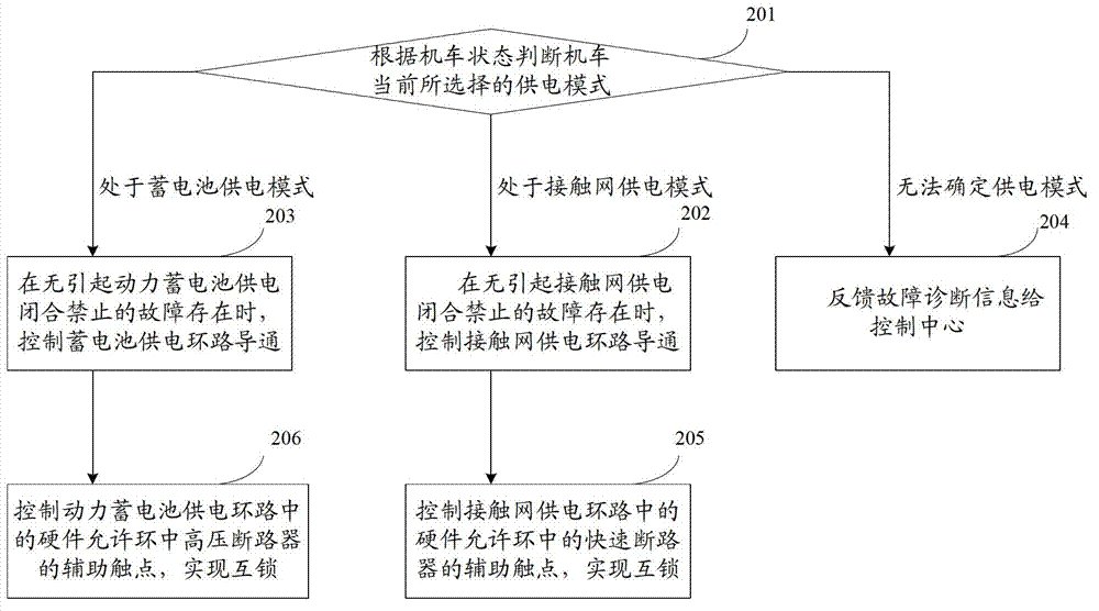
[0059] In practical applications, due to the failure of the power supply mode selected by the locomotive, it is impossible to determine which power supply mode is selected by the current locomotive, and then the method in Embodiment 1 cannot be used for control. In order to solve the above technical problems, the present invention also provides another Dual energy power supply control method such as image 3 The schematic diagram of the method shown, specifically includes:

[0060] Step 201: judge the power supply mode currently selected by the locomotive according to the state of the locomotive;

[0061] Step 202: When the catenary power supply mode is selected, when there is no fault that causes the catenary power supply to be closed and prohibited, control the catenary power supply loop to be turned on;

[0062] Step 203: When the power supply mode of the traction battery is selected, when there is no fault that causes the closure of the power supply of the traction batter...

Embodiment 3

[0069] Corresponding to the dual-energy power supply control method in the first embodiment above, this embodiment of the present application provides a dual-energy power supply control device. Please parameter Figure 4 , which is a device schematic diagram of a dual-energy power supply control device disclosed in Embodiment 3 of the present application. The device includes: a judgment module 301, a first control module 302, and a second control module 303. The working principle of the device will be further introduced below Its internal structure and connection relationship.

[0070] Judging module 301, for judging the power supply mode currently selected by the locomotive according to the state of the locomotive;

[0071] Preferably, the judgment module includes: an identification submodule 301A, a detection submodule 301B and a switching submodule 301C.

[0072] The identification sub-module 301A is used to identify the state of the locomotive according to the mobile com...


PUM


Abstract

The embodiment of the invention discloses a method and device for controlling power supply of double energy sources. The method comprises the steps of: judging a power supply mode selected by a locomotive currently based on a locomotive state; when a contact network power supply mode is selected, controlling break-over of a power supply loop of a contact network at the absence of a fault which results in power supply switch-on prohibition of the contact network; and when a power storage battery power supply mode is selected, controlling break-over of a power supply loop of a power storage battery at the absence of a fault which results in power supply switch-on prohibition of the power storage battery. Through the method disclosed by the invention, the locomotive can select a suitable power supply mode based on the practical condition, and can work normally by switching to the power storage battery power supply mode when no contact network exists so as to enhance application adaptability of an electric locomotive.

Description

technical field [0001] The invention relates to the field of railway locomotives, in particular to a dual-energy power supply control method and device. Background technique [0002] At present, electric locomotives are powered by catenary. However, due to the limitation of catenary network layout in practical applications, there will be no catenary section or catenary without electricity during locomotive operation. In any of the above cases , the electric locomotive will not be able to pull the train because of the loss of power supply, which will cause certain limitations to the application of the electric locomotive and affect the practicability of the electric locomotive. [0003] Based on the above technical problems, it is urgent to provide a new control method to provide two power supply modes for the electric locomotive, and to continue to pull the train in the non-catenary interval or when the catenary is out of power, so as to enhance the practicability of the ele...

Claims


Application Information

Patent Timeline
IPC IPC(8): B60L9/00B61C3/02H02J9/06
CPCY02T30/00Y02T90/16
Inventor 王建荣杨颖高殿柱马晓宁梅曦汪建
Owner ZHUZHOU ELECTRIC LOCOMOTIVE CO
Why Eureka
Try Eureka