Slide switch

A sliding switch and slider technology, which is applied in the direction of electric switches, contact drive mechanisms, seat belts in cars, etc., can solve the problems of miniaturization difficulty and length increase, and achieve the effect of miniaturization

Inactive Publication Date: 2013-07-17
HOSIDEN CORP
View PDF4 Cites 4 Cited by
  • Summary
  • Abstract
  • Description
  • Claims
  • Application Information

AI Technical Summary

Problems solved by technology

[0004] The slide switch is required to be miniaturized, but in the prior art, since the range of motion of the slider 930 of the slide switch 9 is the same as the range of motion of the movable part 51 on the buckle device side of the seat belt, the corresponding movable part 51 The operating range of the slide switch 9 also becomes longer in the sliding movement direction, making miniaturization difficult

Method used


Image

  • Slide switch
  • Slide switch
  • Slide switch

Examples


no. 1 approach )

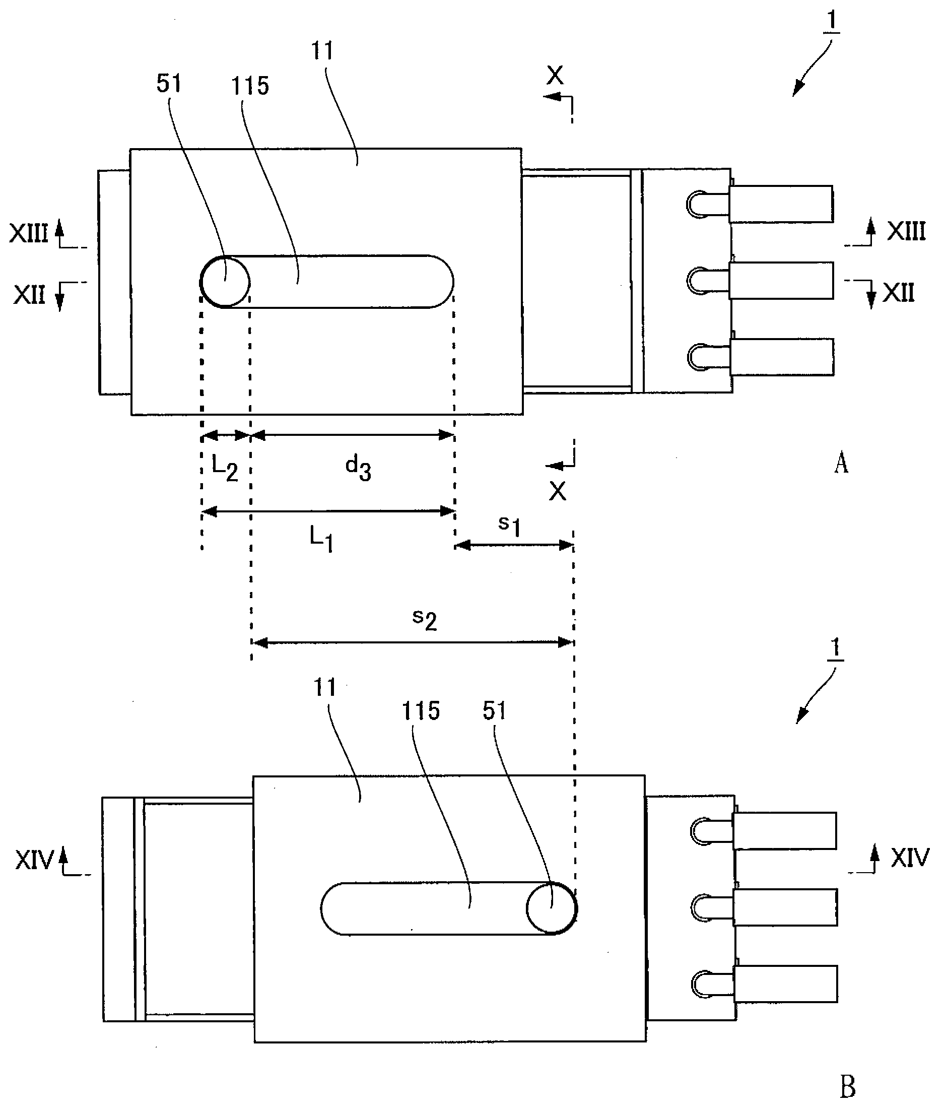
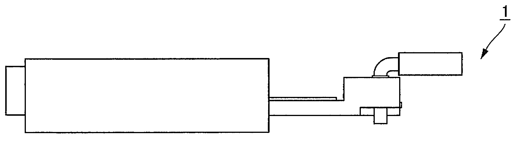
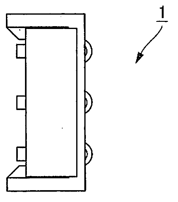
[0027] figure 1 In the front view of the slide switch 1 of the first embodiment showing the slider 11 at the initial position, A indicates the slider 11 at the initial position, and B indicates the slider 11 at the post-operation position. figure 2 A bottom view showing the slide switch 1 of the first embodiment, image 3 represents its left side view, Figure 4 represents its right side view, Figure 5 Indicates its rear view. Image 6 A perspective view of the slide switch 1 viewed from the front side is shown, Figure 7 Represents its exploded perspective view, Figure 8 A perspective view of the slide switch 1 viewed from the back side is shown, Figure 9 Indicates its exploded perspective view. In addition, three wire harnesses 151 to 153 are simultaneously shown in each of several figures, figure 1 and Image 6 In the middle, the movable portion 51 is also shown.

[0028] The slide switch 1 includes a slider 11 , a contact piece 12 , three terminals 131 to 13...


PUM


Abstract

A slide switch includes a body, a slider, a terminal, and an armature. The slider is slidably held in the body and is pushed by insertion of the object to slidingly move. The terminal is provided with a fixed contact point disposed on a surface, facing the slider, of the body along a sliding movement direction. The armature is attached to the slider and is provided with a moving contact point that slides on a fixed contact point disposition surface of the body in association with sliding movement of the slider. The slider is provided with an engagement part to receive an action of a moving part that moves in the sliding movement direction in association with extraction and insertion of the object, and the engagement part is in shape of generating a free running distance in which the slider does not act even when the moving part acts.

Description

technical field [0001] The present invention relates to a slide switch for detecting the pulled-out state and the inserted-engaged state of an object. Background technique [0002] The technique of patent document 1 is known as a prior art of a slide switch. Figure 15 It is an exploded perspective view showing the structure of the slide switch 9 described in Japanese Patent Laid-Open No. 2011-62423 (hereinafter referred to as Patent Document 1). The slide switch 9 includes a main body 920 , a slider 930 slidably held on the main body 920 and slidably moved by being pressed by a movable portion on the side of the snap device, and slidably moved along a surface of the main body 920 facing the slider 930 . The fixed contacts 941 to 943 arranged in the direction, and the movable contact piece 944 which is attached to the slider 930 and slides on the fixed contact arrangement surface of the main body 920 with the sliding movement of the slider 930 . In addition, a stopper 923 i...

Claims


Application Information

Patent Timeline
Patent Type & Authority Applications(China)
IPC IPC(8): H01H15/24H01H15/16
CPCB60R22/48H01H15/10H01H1/365H01H15/14B60R2022/4816A44B11/00H01H3/48A44B11/25H01H15/02
Inventor 山中乡司出崎健二郎小泉浩文
Owner HOSIDEN CORP
Why Eureka
Try Eureka