A slow-wave structure of an angle logarithmically folded slot waveguide

A technology of slow-wave structure and slot waveguide, which is applied to the circuit components of transit-time electronic tubes, can solve the problems of high operating voltage, internal failure, and inability to miniaturize devices, so as to reduce operating voltage, avoid failure, and reduce equipment volume. Reduced effect

Active Publication Date: 2019-12-20
UNIV OF ELECTRONICS SCI & TECH OF CHINA
View PDF4 Cites 0 Cited by
  • Summary
  • Abstract
  • Description
  • Claims
  • Application Information

AI Technical Summary

Problems solved by technology

[0004] The purpose of the present invention is: the present invention provides a slow-wave structure of angle-logarithmic folded groove waveguide, which solves the problem that the existing folded waveguide operates in the high-frequency band, which leads to internal failure due to too high operating voltage and the problem that the device cannot be miniaturized

Method used


Image

  • A slow-wave structure of an angle logarithmically folded slot waveguide
  • A slow-wave structure of an angle logarithmically folded slot waveguide
  • A slow-wave structure of an angle logarithmically folded slot waveguide

Examples


Embodiment 1

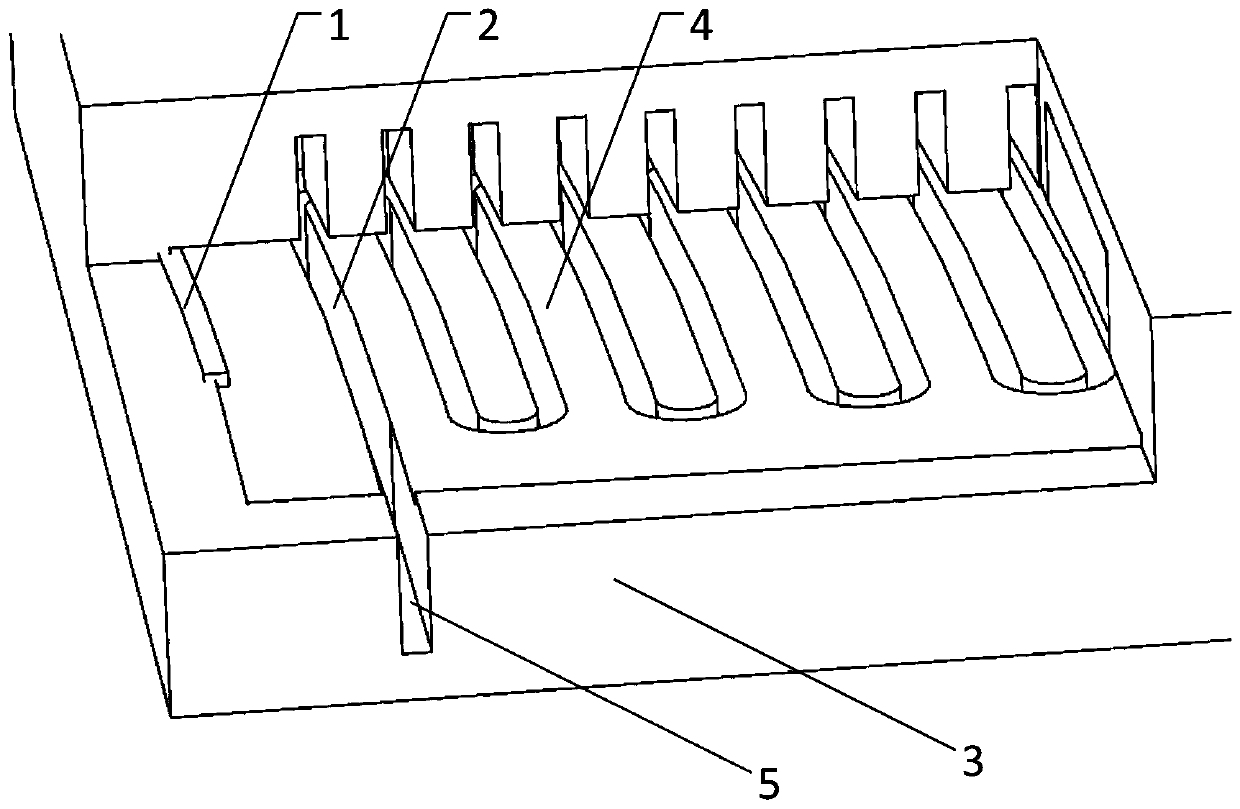
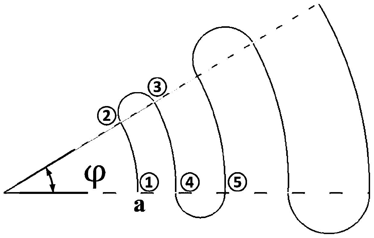
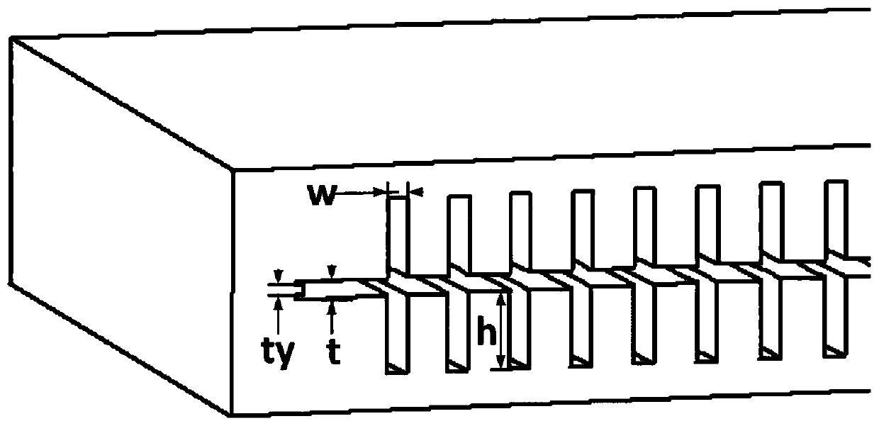
[0035] The cross-section of the angle logarithmic slot waveguide is rectangular, its width W is 0.1 mm, its depth h is 0.3 mm, the thickness t of the radial electron injection channel 4 is 0.08 mm, and its opening angle Greater than slot waveguide opening angle Zhang Jiao Take 4°. The radial emitting surface of the cathode emitter 1 is concentric with the slot waveguide, and the opening angle is arc surface, opening angle It is located at the rightmost end of the radial electron injection channel 4, and its thickness t y It only needs to be smaller than the thickness t of the radial electron injection channel 4 . The port 5 includes an input port and an output port, and the input port and the output port extend vertically to the metal cavity, and their width and depth are equal to the value ranges of the width and depth of the slot waveguide cross section.

[0036] Working principle: In the angle logarithmic slot waveguide, when the electromagnetic wave propagates al...

Embodiment 2

[0039] The cross-section of the angle logarithmic slot waveguide is rectangular, the value of its width W can be 0.14 mm, the value of depth h can be 0.8 mm, and the value of thickness t of radial electron injection channel can be 0.12 mm; the present invention It solves the problem that the existing folded waveguide operates in the high-frequency band due to the high working voltage, which leads to internal failure and the problem that the device cannot be miniaturized, and achieves the generation of high-power electromagnetic waves in the terahertz band, effectively reducing the working voltage of the electric vacuum device, and correspondingly reducing the volume of the equipment. The miniaturization effect of the electric vacuum device is realized.


PUM


Abstract

The invention discloses an angle-logarithmic folded groove waveguide slow-wave structure, which relates to the field of electronic vacuum high-power devices; it comprises two mirror-symmetrical metal cover plates up and down, the metal cover plates are connected by brazing, and the The metal cover plate includes a metal cavity, a cathode emitter arranged on the metal cavity, a slot waveguide etched in the metal cavity, an angular electromagnetic wave channel groove etched on the slot waveguide, and ports arranged at both ends of the slot waveguide , the gap between the upper and lower slot waveguides forms a radial electron injection channel, and the slot waveguide adopts an angle logarithmic slot waveguide that can greatly reduce the voltage in the high frequency band; The problem of internal failure caused by too high and the inability to miniaturize the device has achieved the effect of generating high-power electromagnetic waves in the terahertz band, effectively reducing the operating voltage of the electric vacuum device, and reducing the volume of the corresponding equipment to achieve the effect of miniaturization of the electric vacuum device.

Description

technical field [0001] The invention relates to the field of electronic vacuum high-power devices, in particular to an angle-logarithmic folded groove waveguide slow-wave structure. Background technique [0002] Electric vacuum device is a kind of electronic device with a long history. Since it was invented in the early 20th century, it has been used in various fields of the electronic industry; its main function is to amplify the energy of electromagnetic waves in various frequency bands, so This type of electronic device has irreplaceable influence in the fields of radar, communication, satellite, electronic warfare and so on. Vacuum devices have inherent advantages in terms of power capacity, anti-interference, and anti-irradiation, especially in the terahertz frequency band (0.1-10THz). The high-power electromagnetic waves in this frequency band have important applications in many fields, such as basic fields such as biology, chemistry, and physics, and technical fields...

Claims


Application Information

Patent Timeline
Patent Type & Authority Patents(China)
IPC IPC(8): H01J23/24
CPCH01J23/24
Inventor 王禾欣许多师凝洁李新义何腾龙宫玉彬段兆云巩华荣王战亮路志刚
Owner UNIV OF ELECTRONICS SCI & TECH OF CHINA
Why Eureka
Try Eureka