Camera device and control method thereof, lens unit and control method thereof
A technology of camera equipment and lens unit, which is applied in the field of camera equipment with interchangeable lens and its control, and can solve the problems of difficult lens unit TVAF control and the like
- Summary
- Abstract
- Description
- Claims
- Application Information
AI Technical Summary
Problems solved by technology
Method used
Image

Examples
Embodiment 1
[0029] In the lens-interchangeable camera system of the first embodiment (Embodiment 1) of the present invention, the imaging apparatus transmits the drive start time of the focus lens and the arrival judgment reference time used as the following reference to the camera system including the focus lens In the lens unit, the reference is used to judge whether the focus lens can reach the target position before the arrival judgment reference moment. The lens unit returns the result of the arrival prediction to the imaging device. This transmission (and return) enables focus control with management of the control timing of the imaging device and the lens unit.
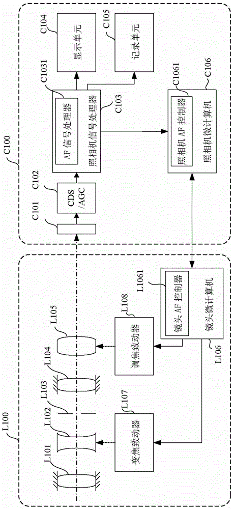
[0030] figure 1 The configuration of the lens-interchangeable camera system of the first embodiment is shown. The lens unit L100 is an interchangeable lens detachably attached to a camera body C100 as an imaging apparatus.
[0031] Light from the subject passes through the imaging optical system inside the lens unit L10...
Embodiment 2
[0114] A second embodiment (Embodiment 2) of the present invention will be described. Embodiment 1 describes the case where the camera body transmits information related to the arrival judgment reference time to the lens unit, and the lens unit predicts whether the focus lens can reach the target position before the arrival judgment reference time, and returns as the arrival prediction the result of. This embodiment will describe a case where the same operations as in Embodiment 1 are realized at a timing different from that in Embodiment 1. The structure of the lens-interchangeable camera system in this embodiment and figure 1 The shown embodiment 1 has the same structure. In addition, the overall flow of TVAF control in this embodiment is the same as image 3 The overall flow of the shown embodiment 1 is the same.
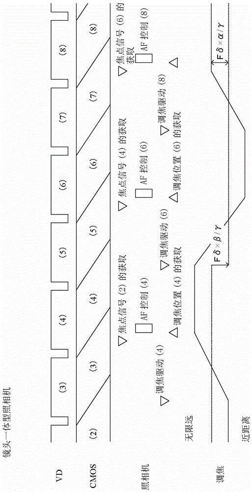
[0115] This example refers to Figure 4 and 5 To mainly explain in the image 3 The reciprocating operation performed in step 302 shown corresponds to the...
Embodiment 3
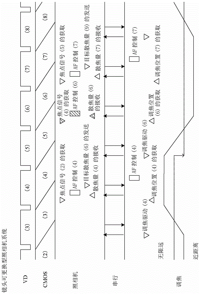
[0149] A third embodiment (Embodiment 3) of the present invention will now be described. This embodiment describes the case where the camera body transmits information on the timing of defocus amount prediction to the lens unit, and the lens unit predicts the actual drive amount of the focus lens at the defocus amount prediction timing, and the defocus amount The result of the focus amount prediction is converted into the defocus amount on the image sensor surface and returned to the camera body. The structure of the lens-interchangeable camera system in this embodiment and figure 1 The shown embodiment 1 has the same structure. In addition, the overall flow of TVAF control in this embodiment is the same as image 3 The overall flow of the shown embodiment 1 is the same.
[0150] This example refers to Figure 6 and 7 To mainly explain in the image 3 The reciprocating operation performed in step 302 shown corresponds to the control performed by the camera microcomputer ...
PUM
 Abstract
Description
Claims
Application Information
 - R&D
- Intellectual Property
- Life Sciences
- Materials
- Tech Scout
- Unparalleled Data Quality
- Higher Quality Content
- 60% Fewer Hallucinations
Browse by: Latest US Patents, China's latest patents, Technical Efficacy Thesaurus, Application Domain, Technology Topic, Popular Technical Reports.
© 2025 PatSnap. All rights reserved.Legal|Privacy policy|Modern Slavery Act Transparency Statement|Sitemap|About US| Contact US: help@patsnap.com