Flexible micro-positioning platform

A micro-positioning platform and flexible technology, applied in the field of machinery, can solve the problems of accumulated error, weak structure, small volume, etc., and achieve the effect of enlarging the scope of the working space, increasing the scope of the working space, and fast dynamic response speed.

Inactive Publication Date: 2013-07-24
HEBEI UNIV OF TECH
View PDF4 Cites 26 Cited by
  • Summary
  • Abstract
  • Description
  • Claims
  • Application Information

AI Technical Summary

Problems solved by technology

[0003] To sum up, most of the currently known flexible micro-manipulators mostly use piezoelectric ceramic direct drive, which is limited to the displacement output that the piezoelectric body can provide, and it is difficult to achieve sufficient operating space at the execution end, while some micro-manipulators Although a certain displacement amplification mechanism has been introduced to increase the range of operating space, the mechanism is complicated, errors are easy to accumulate, and the overall stiffness is reduced, which is easy to cause vibration during the working process; The specific objects are different, but the basic operation sequence is the same. Flexible and precise movement ability is the most fundamental requirement for micromanipulators. However, due to the small size and weak structure of the operation objects, it is necessary to accurately complete some Micro-manipulation is still difficult. Therefore, the design and development of micro-manipulation mechanisms with high precision, high rigidity and the ability to realize actions with more degrees of freedom and the integration with other related operating technologies are the main tasks of current micro-nano precision manipulative technology. direction

Method used


Image

  • Flexible micro-positioning platform
  • Flexible micro-positioning platform
  • Flexible micro-positioning platform

Examples


Embodiment Construction

[0020] The technical solution of the present invention will be described in further detail below in conjunction with the embodiments and accompanying drawings.

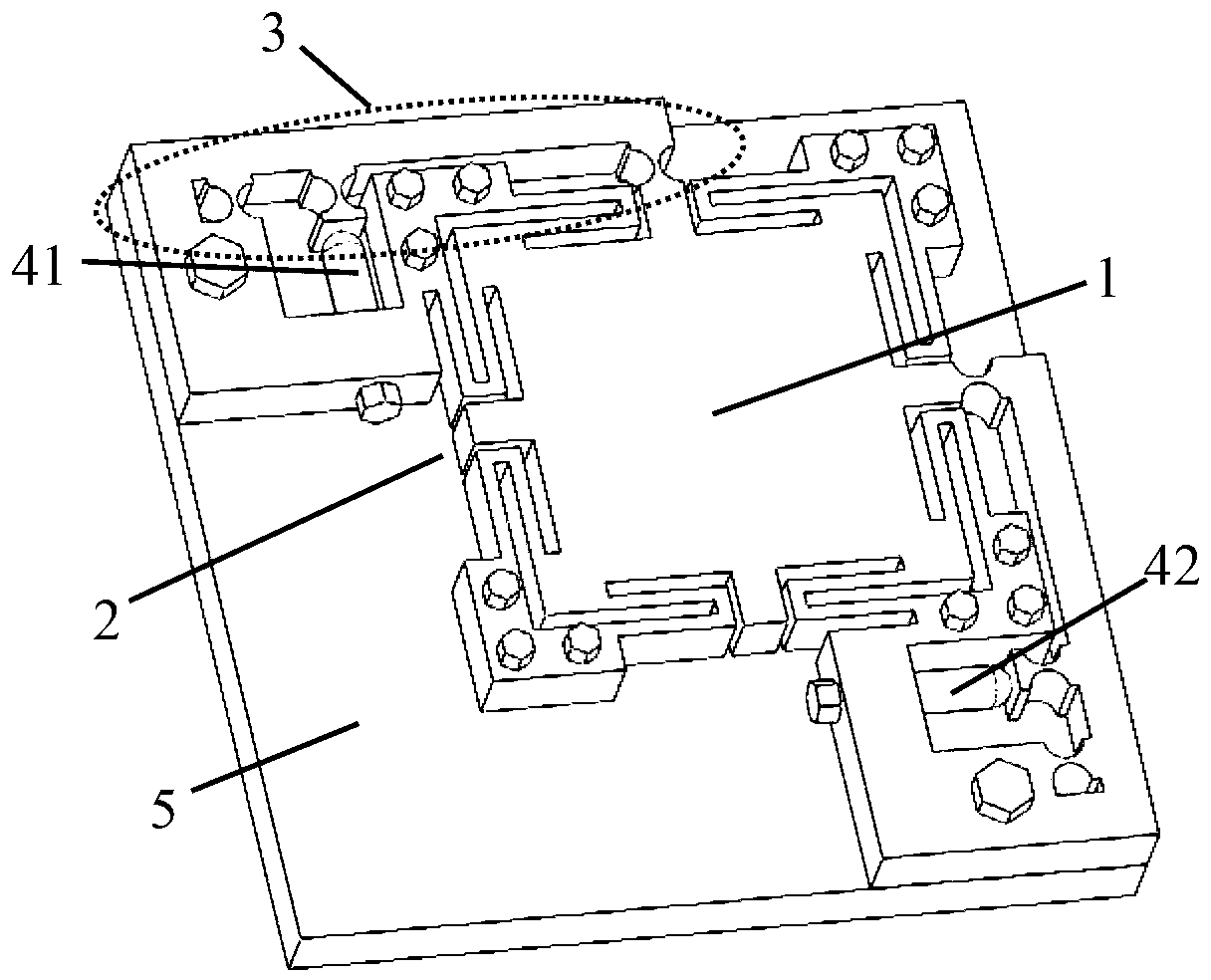
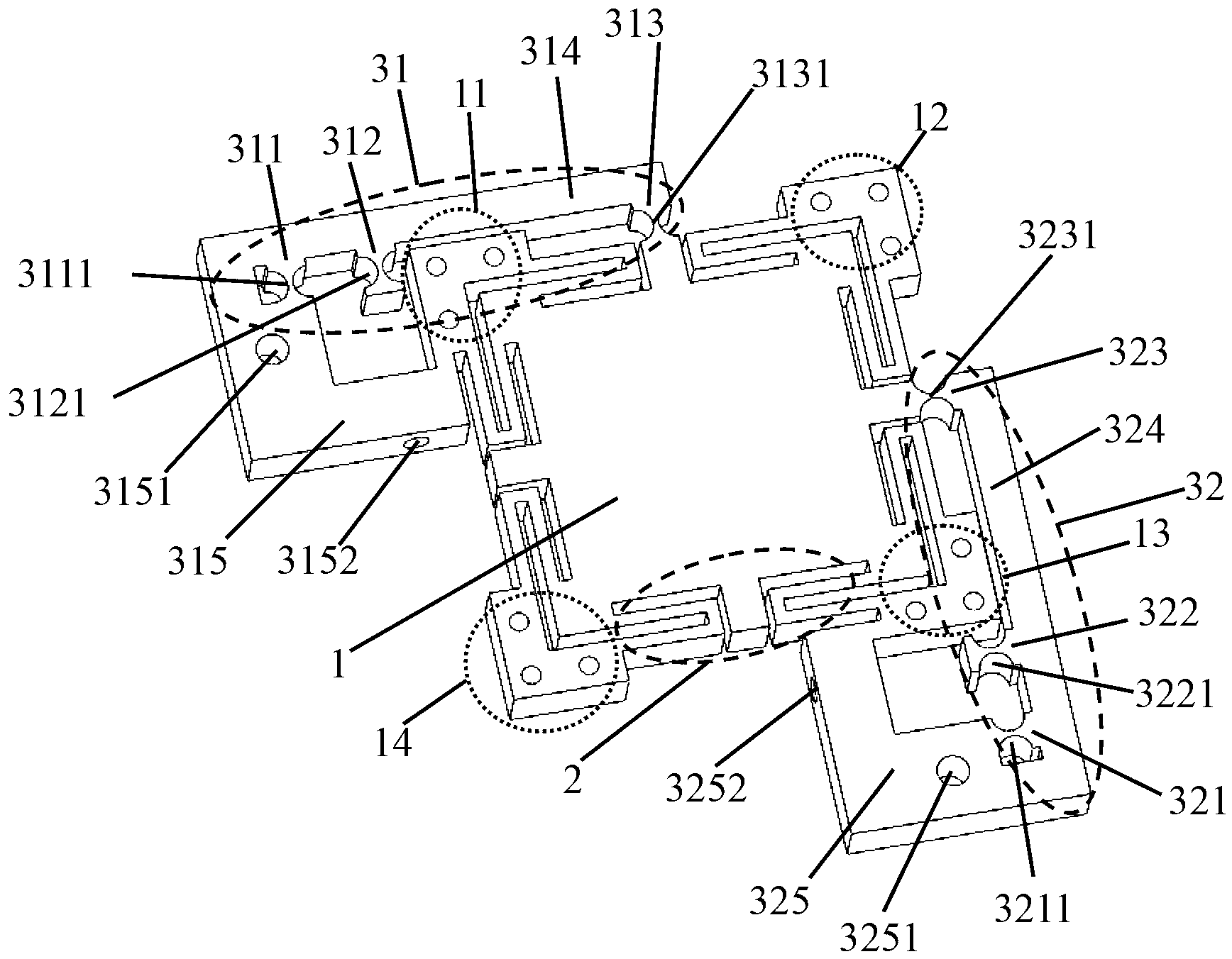
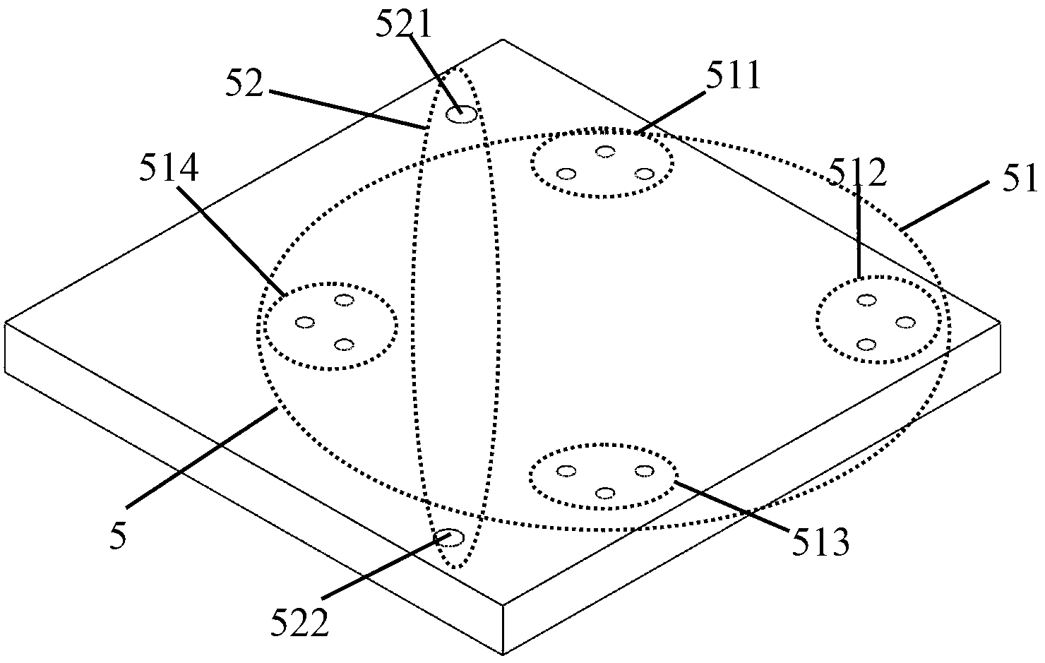
[0021] The flexible micro-positioning platform based on lever displacement amplification designed by the present invention (referred to as the positioning platform, see Figure 1-4 ), which is characterized in that the positioning platform includes a moving platform, four pairs of bow-shaped leaf springs, two flexible lever displacement amplification mechanisms, two piezoelectric ceramic drivers and a base, the moving platform is a square structure, and is distributed on it Supported by four pairs of bow-shaped leaf springs on the four edges, a protrusion is extended outward from the midline position of the four sides of the moving platform, and among the four protrusions, the lower edge of the moving platform and the moving platform The two protrusions on the left edge of the moving platform are vacant, and the two p...


PUM


Abstract

The invention discloses a flexible micro-positioning platform, which is characterized in that the positioning platform comprises a movable platform, four pairs of arched leaf springs, two flexible lever displacement amplification mechanisms, two piezoelectric ceramic drivers and a base, wherein the movable platform is in a square structure and is supported by the four pairs of amplified arched leaf springs distributed on four edges of the movable platform; the fixed ends of the flexible lever displacement amplification mechanisms are in rigid connection with the base by threads; the input ends of the flexible lever displacement amplification mechanisms are abutted against the working ends of the two piezoelectric ceramic drivers; the directions of the two flexible lever displacement amplification mechanisms are respectively parallel with the edge directions of the movable platform connected with the flexible lever displacement amplification mechanisms; the working ends of the two piezoelectric ceramic drivers are supported on the input ends of the two flexible lever displacement amplification mechanisms; the non-working ends of the two piezoelectric ceramic drivers are supported on ''L''-shaped rigid blocks extending from the fixed ends of the flexible lever displacement amplification mechanisms; and the ''L''-shaped rigid blocks are provided with threaded holes used for connecting with the piezoelectric ceramic drivers and the base.

Description

technical field [0001] The invention belongs to a micro-operating system in the mechanical field, in particular to a flexible micro-positioning platform. The micro-positioning platform is based on lever displacement amplification and is mainly used in the field of micro-nano operation. It has two degrees of freedom and can realize two linear translation movements in the working plane. Background technique [0002] Micro-operating mechanism is an important branch of micro-electro-mechanical technology. It has broad application prospects and important research value in the fields of micro-mechanical parts assembly, MEMS assembly and packaging, bioengineering, micro-surgery, and optical fiber coupling operations. At present, molecular scanning microscopes, micro-cameras, micro-actuators, micro-sensors and tele-micro-manipulation robots, which are widely used in the fields of molecular manipulation, bioengineering, medical visualization, and minimally invasive, all belong to thi...

Claims


Application Information

Patent Timeline
Patent Type & Authority Applications(China)
IPC IPC(8): F16M11/04F16M11/18
Inventor 贾晓辉刘今越姜云峰李铁军
Owner HEBEI UNIV OF TECH
Why Eureka
Try Eureka