Heat fin

A thermal fin, side panel technology applied to thermal fins. It can solve the problems of long distance and low heat transfer limit of the vapor chamber, and achieve the effect of wide reflow width, favorable for divergence and condensation, and high heat flux density.

Inactive Publication Date: 2013-07-24
张跃
View PDF7 Cites 6 Cited by
  • Summary
  • Abstract
  • Description
  • Claims
  • Application Information

AI Technical Summary

Problems solved by technology

However, due to the longer distance from the center of the vapor chamber evaporation area to the edge of the evaporation area, the center of the evaporation area of ​​the vapor chamber will evaporate earlier, resulting in a lower heat transfer limit of the vapor chamber

Method used


Image

  • Heat fin
  • Heat fin
  • Heat fin

Examples


Embodiment Construction

[0036] In order to make the above objects, features and advantages of the present invention more comprehensible, specific implementations of the present invention will be described in detail below in conjunction with the accompanying drawings. It should be noted that the present invention is not limited to the following specific embodiments, and those skilled in the art should understand the present invention from the spirit embodied in the following embodiments, and each technical term can be made the broadest based on the spirit of the present invention. understanding. The same or similar components in the figures are denoted by the same reference numerals.

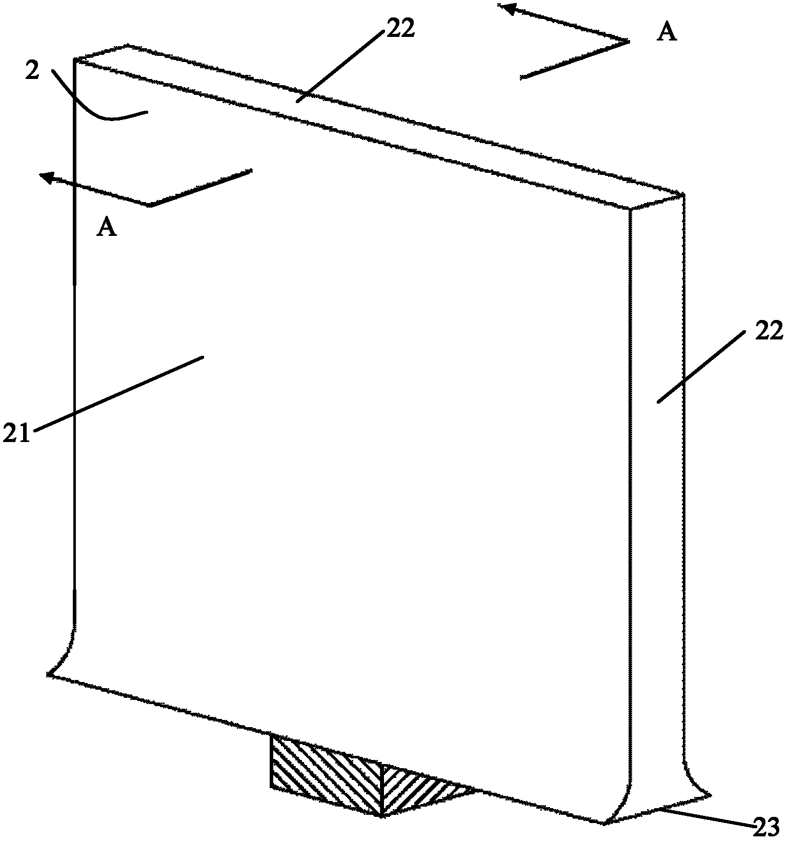
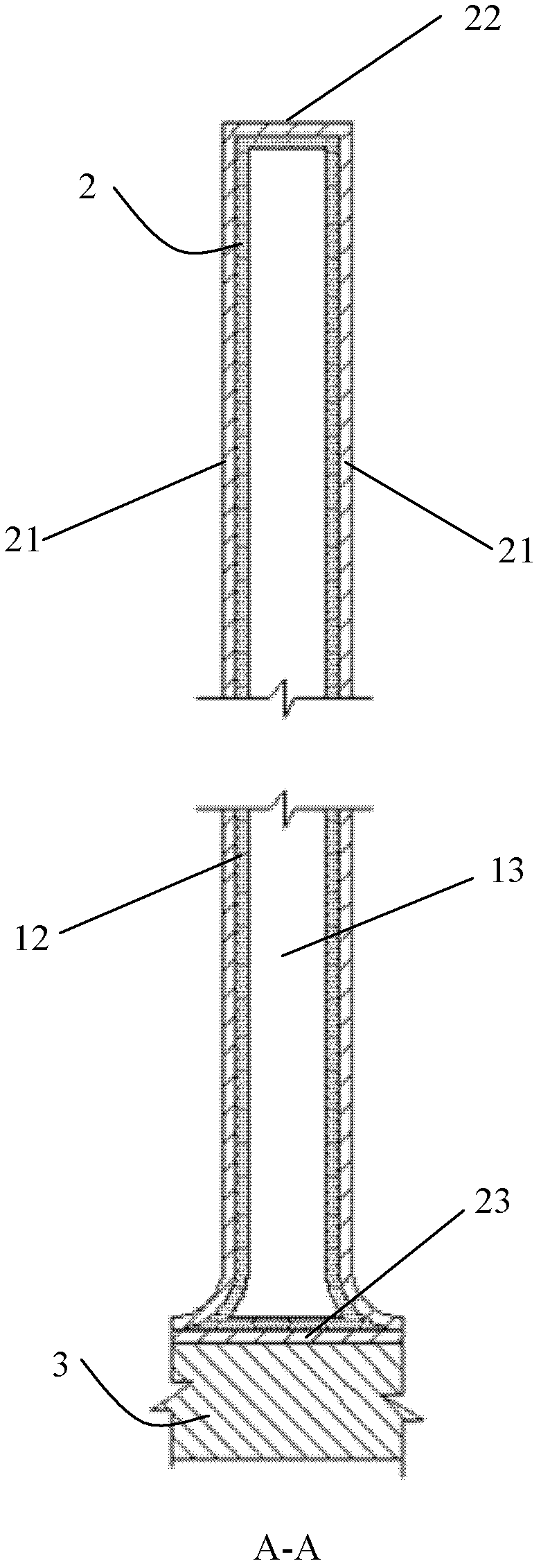
[0037] figure 2 , image 3 The first embodiment of the present invention is shown, as shown in the figure, the heat fin of the present invention includes two side panels 21 forming a hollow plate-shaped casing 2 and frames 22, 23 connecting the two side panels 21, tightly The capillary structure layer 12 attached to...


PUM


Abstract

The invention discloses a heat fin, which comprises two side panels, a frame for connecting the two side panels, a capillary structural layer and a phase changing working medium, wherein the two side panels and the frame form a hollow thin-plate shell; the capillary structural layer is closely attached onto the inner wall of the shell; the phase changing working medium is sealed in the shell; a local part of the edge of each side panel or a local part of the frame is used as an evaporation area, and the rest part of each side panel or the rest part of the shell is used as a condensation area. Due to the adoption of the heat fin, the area of a steam conveying passage, the reflux width of the liquid working medium and the direct heat radiation area of the condensation area are increased, the distance from the center of the evaporation area to the edge of the evaporation area is shortened, the heat conduction limit is greatly improved, and a higher heat flow density is obtained.

Description

technical field [0001] The invention relates to a phase change heat transfer device, in particular to a heat-wing. Background technique [0002] Compared with solid metals with high thermal conductivity, phase change heat transfer devices have higher equivalent thermal conductivity and better heat dissipation performance. It relies on the phase change of its internal liquid working medium to conduct heat, and has high thermal conductivity and excellent isothermal properties. And other advantages, are widely used in industry. At present, heat pipes and vapor chambers are more commonly used heat dissipation devices in phase change heat transfer devices. [0003] see figure 1 A typical heat pipe consists of a tube shell 11, a capillary structure 12 and a phase-change working medium 13 sealed in the tube. The manufacture of the heat pipe usually first vacuumizes the inside of the tube and then fills it with a suitable phase-change working medium 13, so that the capillary stru...

Claims


Application Information

Patent Timeline
Patent Type & Authority Applications(China)
IPC IPC(8): F28D15/04
CPCF28D15/04
Inventor 张跃
Owner 张跃
Why Eureka
Try Eureka