Gypsum line lamp strip light guide plate mounting equipment

A technology for installing equipment and light guide plates, applied in the field of light guide plates, can solve problems such as the length of the light guide plates, and achieve the effects of low power consumption, uniform light, and high luminous efficiency

Inactive Publication Date: 2021-04-30
沭阳百思得电子商务有限公司
View PDF0 Cites 0 Cited by
  • Summary
  • Abstract
  • Description
  • Claims
  • Application Information

AI Technical Summary

Problems solved by technology

[0002] The light guide plate is an optical-grade plate that uses laser engraving, V-shaped cross grid engraving, and UV screen printing technology to print light guide points on the bottom surface of the acrylic plate with a high-tech material with a very high refractive index and no light absorption. The light guide plate has luminous High efficiency, low power consumption, uniform light, safety and environmental protection, etc., are widely used in fluorescent lamps, display screens, and even the light strips in the indoor gypsum line are also equipped with light guide plates, but in the decoration process, the light guide plate It is long and requires the constructor to climb up to a high place for measurement, cutting and installation, and there is a certain risk of falling from a high place. Therefore, it is necessary to install a gypsum line lamp with a light guide plate installation equipment to improve the above problems

Method used


Image

  • Gypsum line lamp strip light guide plate mounting equipment
  • Gypsum line lamp strip light guide plate mounting equipment
  • Gypsum line lamp strip light guide plate mounting equipment

Examples


Embodiment Construction

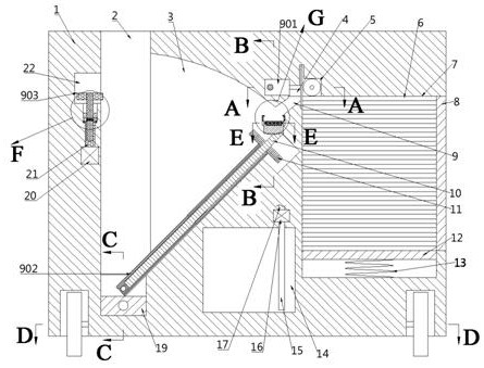
[0020]Bonded belowFigure 1-8The present invention will be described in detail, in which it is convenient for the description, the orientation of the following statement is as follows: The above-mentioned left and right directionsfigure 1 The projection relationship of the projection is consistent with the front and back and so on.

[0021]A plaster line lamp belt light guide plate mounting apparatus according to Figs. 1-8, includes a fuselage 1, a light-conductive plate chamber 7 having an opening to right in the right wall, the light guide plate chamber 7 The right side is provided with a door 8 for closing the light guiding plate chamber 7, and the light guiding plate cavity 7 is fixedly provided with a bottom plate compression spring 13, the bottom plate compression spring 13 away from one end of the bottom wall of the light guide plate chamber 7. The bottom plate 12 is provided, and the top wall of the bottom plate 12 is disposed in contact with a light guide plate 6, and the light...


PUM


Abstract

The invention relates to the related field of light guide plates, in particular to gypsum line lamp strip light guide plate mounting equipment. The gypsum line lamp strip light guide plate mounting equipment comprises a machine body, a light guide plate cavity with a rightward opening is formed in the right wall of the machine body, a door used for sealing the light guide plate cavity is arranged on the right side of the light guide plate cavity, and a bottom plate compression spring is fixedly arranged on the bottom wall of the light guide plate cavity. The light guide plate can move in a mechanical arm through a roller, then glue can be smeared on the light guide plate through the mechanical arm, and manual gluing is avoided; meanwhile, the purposes of uniform gluing, timely mounting, prevention of glue drying in advance and the like can be achieved by gluing while mounting is carried out; meanwhile, a push rod enters the machine body due to the fact that the push rod is close to the wall, the corners of the light guide plate are cut, and the purpose of judging the wall corner to enable the light guide plate to be attached to the wall corner is achieved; and meanwhile, a lead screw nut is used for driving the light guide plate to ascend and descend, so that danger is prevented from generating when a constructor climbs to a high position.

Description

Technical field[0001]The present invention relates to the field of light guide plates, in particular a plaster line lamp with a light guide plate mounting device.Background technique[0002]The light guide plate is a laser engraving, V-type cross grid engraving, and UV mesh printing technology puts extremely high refractive index and non-absorbing high-tech materials in the bottom of the acrylic plate, the light guide point optical grade sheet, the light guide plate has luminous High efficiency, low power consumption, uniform light, safe and environmental protection, etc., is widely used in fluorescent lamps, on the display, and even the light guide plates are also applied to lamp strips in the indoor plaster line, but during the decoration process, light guide plates For longer, it is necessary for the construction to climb the height to measure, cut, and installed, with a certain risk of falling, so it is necessary to set a gypsum line lamp with light guide plate mounting equipment ...

Claims


Application Information

Patent Timeline
Patent Type & Authority Applications(China)
IPC IPC(8): B26D1/14B26D5/08B26D7/06B05C5/02B05C13/02F21V17/10
CPCB05C5/0208B05C13/02B26D1/14B26D5/08B26D7/06F21V17/101
Inventor 孙奥信
Owner 沭阳百思得电子商务有限公司
Why Eureka
Try Eureka